Ball Screws and Nuts Glossary
A comprehensive load calculation that accounts for multiple force components. Included in these components are: weight of the sliding mechanism (vertical), weight of the sliding mechanism multiplied by the coefficient of sliding friction (horizontal), direct forces resisting the linear motion (i.e. cutting tools), other applicable force components.

A load that is parallel to the centerline of the screw shaft and equally distributed around the mounting surface. It is the recommended methodof attaching the load to the the ball nut.
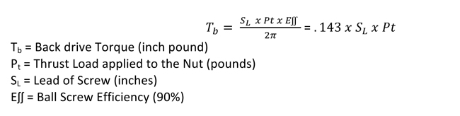
The torque produced through the screw shaft by a thrust load on the ball nut. Ball screws can coast or back drive due to the high efficiency of the mechanism (90%). If back-driving is not acceptable, a method to resist the overturning back-driving systemic torque, such as a brake, will be required to hold the load. If back-driving is desired, the lead of the screw should be at least 1/3 of the screw diameter. Ideally the lead should be equal to the screw diameter. This calculated torque is the minimum amount of braking torque to hold the load in position.
The axial free motion between the nut and the screw. It determines the amount of lost motion between the nut and screw on a horizontal application. The backlash on ball nuts ranges from .005" to .015", depending on the screw size.
(Ball Circle Diameter) The theoretical cylinder passing through the center of the balls bearings when they are in contact with the ball screw and ball nut races.
A black oxide finish is provided on ball screws to help prevent corrosion during shipping and brief storage. Long-term corrosion resistance is accomplished by the rust inhibiting properties of the screw lubricant. In applications with extreme environments, additional coatings such as nickel, hard chrome, zinc or other coatings can be applied. Contact Joyce/Dayton for detailed specifications.
(Life Expectancy) This is the total accumulated inches of travel, under constant load, of a clean and properly lubricated screw and nut before first evidence of fatigue develops. It is expressed in inches of travel. Ball screw life is rated similarly to ball bearing life - in terms of 1,000,000 inches of travel under stated and rated loads.
This is the ability of the screw shaft to withstand compressive forces without buckling. The fundamental limit occurs when the compressive load exceeds the elastic stability of the screw shaft, resulting in bending and buckling of the screw. This mode of failure can only occur when the screw shaft is in compression. Joyce/Dayton recommends limiting the maximum compressive load to 80% of the calculated column load strength.

This is a load that tends to compress the screw or buckle the screw shaft. Consideration must be given to column load limitations when screws are used in compression.
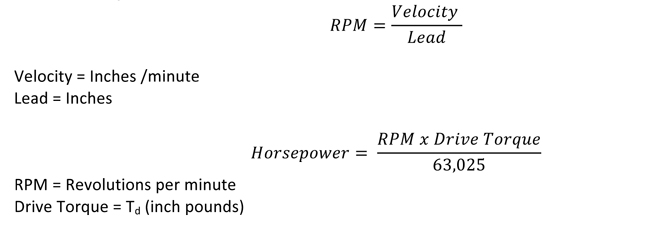
This is the theoretical linear velocity (inches/minute) which excites the natural frequency of the screw. As the speed of the screw approaches the natural frequency (critical speed), the screw shaft begins to resonate. This resonance occurs whether the screw or the nut rotates and regardless of the screw orientation. Joyce recommends limiting the maximum linear velocity to 80% of the calculated critical speed value.

This is the number of inches the ball screw will travel over a given number of years of service.

The amount of torque required by the ball screw to move the load. This torque does not take into account any inertial loading required for acceleration.

This is the maximum thrust load under which the ball screw assembly will achieve a minimum of 1,000,000 inches of travel before first signs of fatigue are present.
(Moment Load) This is a load that tends to rotate around the screw imposing a non-axial load on the screw and nut assembly. Eccentric loads reduce the rated life of ball screws and nuts. They are not recommended.
(Moment Load) This is a load that tends to rotate around the screw imposing a non-axial load on the screw and nut assembly. Eccentric loads reduce the rated life of ball screws and nuts. They are not recommended.
This is the ability of a ball screw to convert torque to thrust, expressed as a percentage. Ball screws are typically 90% efficient.
(Bearing mount support configuration) This refers to the method by which the ends of the screws are supported. The end fixity describes the bearing configuration being used to support the rotational axis of the screw. End fixity combinations are determined as a result of critical speed, column loading, and system stiffness calculations. Fixed-Fixed supports provide the greatest support and Fixed-Free supports provide the least support.
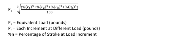
This is a calculated load value used for applications in which the load is not constant throughout the entire stroke of travel. Use the maximum load value when sizing drive components for systems.
The axial distance the screw or nut travels in one revolution.
(Accuracy) The difference between the actual distance traveled and the theoretical distance traveled based on the lead of the screw. The lead error for a standard screw will not exceed +/- .007 inches per foot. Lead error is cumulative based on the actual length of the ball screw thread.
Use this formula when evaluating loads other than the rated load of the ball screw and ball nut. It is based on the inverse cube ratio. When operating at ½ the rated load, life will be increased to 8 times standard life. When operating at twice the rated load, life will be reduced to 1/8 of the standard life.
(Rated Load/Actual Load)3 x 106 = life of assembly under actual load
Lubrication is required to achieve optimum life for a ball screw assembly. Ball screws that are not lubricated can experience up to 90% reduction in calculated life. In general, standard lubrication practices for anti-friction rolling element bearings apply. Grease, oil, or dry film lubrication can be used. Many ball nuts are equipped with 1/8-27NPT lube ports machined into the nut body.
Proper lubrication of ball screw assemblies is critical to maintaining optimum efficiency and life. It is most ideal to introduce the lubricant directly into the ball nut. Lubrication ports can be found in various locations on the ball nut or flange, depending on the specific product. A 1/8-27 NPT lubrication port is located on most ball nuts, but some units have a lubrication port located on the flange, or in the external threads of the ball nut. A Zerk fitting is available on the outside of a few ball nuts.
Joyce/Dayton offers full service machining capabilities to supply screw assemblies that are ready for installation. We offer standard end machining that can accommodate our line of bearing blocks as well as custom machining to meet your specific mounting requirements. Screws can also be supplied cut to length with no machining.
The outside diameter of the screw thread.
(Synchronous Screws) Used when multiple screws are being driven by a single drive in order to keep the screws synchronized. To minimize operational misalignments, lead errors are matched at the factory.
Most ball screws and nuts are made from alloy steel and case hardened to Rc 56 (minimum).
(Root Diameter) The diameter of the screw shaft as measured at the bottom of the ball thread track. This diameter is used in column load and critical speed calculations. Minor diameter is also a consideration in support bearing selection.
The distance from one thread on a screw to a corresponding point on the next thread parallel to the screw axis. Pitch and lead are equal on single start screws.
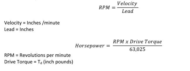
The power to drive a ball screw assembly is a function of the required drive torque and motor R.P.M. Horsepower should be calculated based on the maximum torque required during stroke or cycle. The highest torque requirements generally occur during acceleration, due to inertial loading.
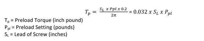
The additional torque required to overcome the frictional components of the preload force. This additional torque needs to be added to the drive torque in order to calculate the required torque for constant velocity.
A method of eliminating backlash in a ball screw assembly. This is accomplished by the use of one group of ball grooves in opposition to another. Preloading increases stiffness (resistance to deflection) and provides for accurate positioning with very little increase in applied torque or load capability.
This is a coiled spring that conform to the ball screw thread. It is installed in the inactive part of the ball nut. The spring is inactive during normal operation and it does not contact the screw, however, in the rare event that the balls are lost from the ball nut, the safety spring assumes the load and prevents the nut from “free falling” down the screw. The spring is not designed to maintain normal operation and the ball screw should be taken out of service after the first engagement of the safety spring. Safety springs are available for all ball screws, but they are not mandatory unless the screw is being used to lift, support, or otherwise transport people. Please contact Joyce/Dayton with your specific requirements
The number of independent threads on the screw shaft. The lead on the screw is calculated by dividing the threads per inch by the number of starts.
This is extremely important in minimizing screw vibration. Our ball screw stock is straight to 0.010 inches per foot. Not to exceed .025 inches over the entire length.
The process of selecting a unique ball bearing size for reducing backlash to as little as .001 inches.
(Radial Load) A load that is applied perpendicular to the screw shaft. This type of load will also reduce the rated life of the ball screw and nut assembly.
This is the maximum non-operating load capacity above which permanent damage of the ball track occurs.
This is a load that tends to stretch that ball screw. It is the preferred mode of attaching the load because it eliminates column loading as a limiting factor on the screw.
Wiper kits are available for all standard ball screw models. The nylon brush wiper is designed to keep large particles from entering the ball nut, however, for harsh environments, bellows boots are also recommended.
Wiper kits for larger ball nuts, 1 1/2" diameter and larger are mounted internally. These wiper kits include 2 wipers and 2 snap rings. When wipers are specified a groove for the retaining ring is machined into the internal diameter of the ball nut to accomocate the assembly of the wiper into the ball nut.
Wipers kits for smaller ball nuts are assembled to the external surface of the ball nut. These kits include (1) cap for the back of the ball nut, and (2) bristle wipers, one for each end. There are several possible methods of attaching these to the ball nut depending on the customer's mounting configuration. Contact sales@joycedayton for additional information.
General Glossary of Terms
This anti-backlash device is best suited for light dynamic loads (1/3 jack capacity or less) and full jack capacity for static loads. A split gear and dowel pins maintain gear alignment. Adjust by tightening the sleeve (housing) cap. These typically reduce endplay to 0.010” – 0.015” without increasing torque. Available on Translating and some KFTN models, 500-pounds to 75-tons (upright and inverted). Anti-backlash Devices
This anti-backlash device is best suited for medium dynamic loads (1/2 to 3/4 jack capacity) and full jack capacity for static loads. This design incorporates a hardened steel plate pinned to the top of the internal gear and a secondary nut placed above the steel plate. Setting the backlash is accomplished by tightening the dog point set screws located inside the secondary nut. The set screws are externally adjustable. These typically reduce endplay to 0.008” – 0.012” without increasing torque. Available on Translating models, 25-tons to 100-tons. Anti-backlash Devices
This anti-backlash devicecapable of handling full jack capacity in dynamic as well as static conditions. It allows the gear teeth to remain intact and therefore retain their full load carrying capacity. Adjust endplay by tightening the sleeve (housing) cap. These typically reduce endplay to 0.008” – 0.012” without increasing torque. They are available on upright and inverted translating models, 2-ton to 150-ton. Anti-backlash Devices
This is a thin, dense chrome finish, which increases resistance to wear and corrosion, and improves lubricity. It can also be applied to stainless steel components for superior corrosion resistance. This thin coating has little effect on the fit of mating components.
A uniform coating process that increases the corrosion resistance and wear properties of aluminum housings. It will not flake or peel.
When a jack is loaded in compression the load pushes the lifting screw toward the jack and the length of the slender column of the lifting screw and the mounting configuration limits the load carrying capacity. Refer to Column load charts for specific jacks or use the JAX Online software to determine the load capacity in a specific application.
ComDRIVEs® combine a screw jack or electric cylinder, motor and gear reducer into a single compact unit. They are available in 2-ton to 30-ton capacities for machine screw and, ball screw jacks and in 2.5-ton to 20-ton capacities for electric cylinders.
When a jack is loaded in compression the load pushes the lifting screw toward the jack and the length of the slender column of the lifting screw and the mounting configuration limits the load carrying capacity.
A term used to describe jacks or actuators on which motors are directly mounted without any intermediate gear reduction. Joyce/Dayton offers standard NEMA motor mounts in 2-ton to 20-ton jacks with 56C through 210TC motor mounts. We also offer direct drive operation on integrated actuators with have a 56C mounting flange. When specifying direct drive solutions for your application it is important to consider the input torque a direct drive motor must deliver at start up.
A double-clevis jack has pivots or clevises at both ends: one on the screw tip and one on the end of the protection tube. This tends to weaken it as a column by creating eccentric loads on the screw. This eccentricity tends to increase with greater distance and higher loading. For this reason, double clevis jacks are limited both in capacity and maximum length.
A thin, uniform coating. When applied to jack housings or to worm and pinion input shaft, it provides superior corrosion resistance and improved wear resistance while having little effect on the fit of mating parts.
A device that can be mounted to jacks to allow accurate position sensing within increments of 0.001”. The encoder combines with your control system to monitor screw travel, number of revolutions, and travel limits.
Follower nut assemblies allow customers to gauge the wear on the wormgear screw thread of translating jacks and on the traveling nut screw thread of KFTN jacks. This allows customers to replace the nut before its threads wear too thin to support the design load. These assemblies generally consist of a gear nut or traveling nut pinned to a second nut of dissimilar material. A preset gap separates the two nuts. As the wormgear or traveling nut threads wear, the preset gap narrows. The assembly is replaced when the gap measurements reaches the design limit. Follower nut assemblies are designed for specific applications. Contact us at sales@joyce/Dayton.com for more information.
Guided loading is often termed “fixed-fixed” loading. With guided loading, both ends or the column are rigidly held – the jack body is bolted firmly to a sturdy base, and the load travels on slides, bearings or other means. The guides should be snug enough to prevent any side load or moment load from reaching the screw.
(RPM x Load (lbs.) x Operating Torque Constant + Tare Torque)/63065 = Horsepower. Check out this example calculation.
International Protection Rating, which consists of the letters IP followed by two numbers. The first number represents resistance to the ingress of solids and the second number represents the resistance of ingress of liquids. For instance IP65 is dust tight (6) and resistant to jets of water (5); IP54 is dust resistant (5) and resistant to splashes of water (4).
Browser-based JAX® Online Software includes all the information needed to specify the right components for specific applications. It can be used to specify jack and electric cylinders based on load, travel speed and rise. Register at Joycedayton.com or login today to use thei time-saving tool..
Keyed jacks include a key, fixed to the jack housing and inserted into a keyway milled into the lifting screw, which forces the lifting screw to translate without rotating. They are used in applications where rotation of the load cannot be restrained.
Keyed for traveling nut jacks (sometimes referred to as rotating screw jacks, KFTN) feature a lifting screw keyed to the wormgear as a single unit, forcing the lifting screw to rotate, but not translate. A flanged traveling nut, attached to the load, is driven by the rotation of the lifting screw. This type of jack is ideal for applications that cannot accommodate a screw protection tube or that require a flush mount.
An exclusive paint process that protects against corrosion due to harsh outdoor environments. It incorporates rigorous surface preparation with a premium epoxy primer and topcoat and stainless steel hardware resulting in a durable, corrosion-resistant finish that is in high demand on antenna jacks, solar actuators, mining industry jacks and jacks used in coastal installations.
The distance a jack and actuator needs to move a load.
Unique serilal numbers are located on the serial tag or etched into the housing of Joyce Dayton products.
This coating provides a hard, non-toxic finish. It is comprised of a two-part, lead-free epoxy primer with a two-part polyamide epoxy topcoat (which incorporates 316 stainless steel leafing pigment). It is approved by the USDA for use where incidental food contact may occur.
When a jack is loaded under tension the load pulls the lifting screw away from the jack .When tension loaded, the jack retains full rated load capacity.
These jacks include a driven worm, which acts on an internal wormgear, which in turn drives a lifting screw to extend or retract. As the lifting screw translates through the body of the jack, inherent screw rotation is prevented by an attached load or mounting structure that is anchored to resist rotation.
In a trunnion mounting arrangement, the screw has a pivot on the end and the jack body is mounted on a large pivoting frame, or trunnion. This type of mounting is particularly common in the antenna industry. In practice, the pivot should be as close to the centerline of the internal nut as design permits. This will eliminate moment loads caused by loose threads.
If the screw is the only support for the load, it is considered unguided. In this case, the screw must be large enough to support the load and prevent buckling.
(Root Diameter) The diameter of the screw shaft as measured at the bottom of the ball thread track. This diameter is used in column load and critical speed calculations. Minor diameter is also a consideration in support bearing selection.
A coating that uses a combination of flouropolymer lubricants and resin binders, significantly reduces the coefficient of friction of components and offers excellent corrosion protection and good chemical resistance. The application of this coating has little effect on the fit of mating parts.
This coating provides protection against corrosion, increases surface lubricity, and improves the aesthetic appearance of components. The effect it has on the fit of mating components is dependent on the thickness of its application.
Machine Screws and Nuts Glossary
A load that is parallel to the centerline of the screw shaft and equally distributed around the mounting surface. It is the recommended method of attaching the load to the nut.
(End Play) The axial free motion between the nut and the screw. It determines the amount of lost motion between the nut and screw on a horizontal application.
There is no formula available to calculate the life of a machine screw. If a calculated life is required, specify a ball screw which has a predictable life based on the life of the ball bearings.
This is the ability of the screw shaft to withstand compressive forces without buckling. The fundamental limit occurs when the compressive load exceeds the elastic stability of the screw shaft, resulting in bending and buckling of the screw. This mode of failure can only occur when the screw shaft is in compression. Joyce/Dayton recommends limiting the maximum compressive load to 80% of the calculated column load strength.
This is a load that tends to compress the screw or buckle the screw shaft. Consideration must be given to column load limitations when screws are used in compression.
This is the theoretical linear velocity (inches/minute) which excites the natural frequency of the screw. As the speed of the screw approaches the natural frequency (critical speed), the screw shaft begins to resonate. This resonance occurs whether the screw or the nut rotates and regardless of the screw orientation. Joyce recommends limiting the maximum linear velocity to 80% of the calculated critical speed value.

Relationship between operation time and rest time. The allowable duty cycle for machine screws is based upon several application variables such as load, speed, and temperature. Consideration must be given to the severity of the duty cycle during the product selection phase. Contact [email protected] for more information.
This is the thrust load which the screw assembly is able to move without exceeding the column strength of the lifting screw.
(Moment Load) This is a load that tends to rotate around the screw imposing a non-axial load on the screw and nut assembly. Eccentric loads reduce the lifr of machine screws; they are not recommended.
This is the ability of a machine screw to convert torque to thrust. Efficiencies that are ≤ 30% tend to be self-locking (in the absence of vibration).
(Bearing mount support configuration) This refers to the method by which the ends of the screws are supported. The end fixity describes the bearing configuration being used to support the rotational axis of the screw. End fixity combinations are determined as a result of critical speed, column loading, and system stiffness calculations. Fixed-Fixed supports provide the greatest support and Fixed-Free supports provide the least support.
The axial distance the screw or nut travels in one revolution.
(Accuracy) The difference between the actual distance traveled and the theoretical distance traveled based on the lead of the screw. Lead error is 005 in./ft. up to 2 ½ inch diameter, and .008 in./ft. up to to 6 inches diameter. Lead error is cumulative based on the actual length of the machine screw thread.
Lubrication is required to achieve optimum operation of machine screw assembly. Apply a NLGI grade #1 grease to the screw thread and nut.
Joyce/Dayton offers full service machining capabilities to supply screw assemblies that are ready for installation. We offer standard end machining that can accommodate our line of bearing blocks as well as custom machining to meet your specific mounting requirements. Screws can also be supplied cut to length with no machining.
(Synchronous Screws) Used when multiple screws are being driven by a single drive in order to keep the screws synchronized. To minimize operational misalignments, lead errors are matched at the factory.
(Root Diameter) The diameter of the screw shaft as measured at the bottom of the thread. This diameter is used in column load and critical speed calculations. Minor diameter is also a consideration in support bearing selection.
The distance from one thread on a screw to a corresponding point on the next thread parallel to the screw axis. Pitch and lead are equal on single start screws.
The number of independent threads on the screw shaft. The lead on the screw is calculated by dividing the threads per inch by the number of starts.
Self-Locking screws require power to move in either direction. They hold position when power to the system is off.
(Radial Load) Load that is applied perpendicular to the screw shaft. This type of load is not recommended for dynamic loads. Static side loads are limited. Contact[email protected] for specific information.
This is the maximum non-operating load capacity.
This is a load that tends to stretch that machine screw. It is the preferred mode of attaching the load because it eliminates column loading as a limiting factor on the screw.
The power to drive a machine screw assembly is a function of the required drive torque and motor R.P.M. Horsepower should be calculated based on the maximum torque required during stroke or cycle. The highest torque requirements generally occur during acceleration, due to inertial loading.
Bellows and Covers Glossary
Round bellows used to cover screws, rods, pistons or other round elements.
An extended element on bellows ends that are used to attach bellows and covers to a structure. Hose clamps are used to hold collars in place.
A more complex end condition for bellows and covers. It consists of a collar with a flange attached. Users may attach the end condition via the collar of the flange portion of the end condition.
Each segment of a sewn bellows profile consisting of two panels stitched together. Bellows and way covers are constructed of multiple convolutions assembled to meet the required extended length.
Curtain covers are flat bellows and may incorporate stiffeners to help hold their original shape and allows them to be mounted vertically or horizontally. Typical applications are to screen an area to prevent accumulation of debris in a recess or to provide protection in a single plane.
A flat surface end condition on bellows and covers. This end is clamped or bolted to the supporting structure.
One or both flange ends can be provided with a hole pattern to accommodate mounting. Customers must specify the hole pattern. This option can be used with our without the steel back-up flange.
Hose clamps are used to attach round bellows to the customer’s structure. They are provided standard with each round bellows.
These bellows are typically mounted vertically. They are constructed from polyester
Sewn tabs are an added feature used to stabilize long vertical bellows and covers. These tabs, added to alternate convolutions, prevent undue stress on seams and sagging at the top of the bellows or cover. The need for sewn tabs is dependent on both the length and size of the bellows or covers. Contact Joyce/Dayton with questions about your specific application.
These are internal stiffener guides are used to support non-vertical bellows and to prevent the internal diameter for contacting the shaft or screw they are protecting. Non-circular stiffener guides are sometimes used to support long horizontal way covers. These guides are fitted between the sewn convolutions of square or rectangular way covers.
The axial distance the screw or nut travels in one revolution.
These flanges are used to provide stiffness when mounting the flange ends on way covers and bellows. Customers may specify a mounting hole pattern for back-up flanges by providing a drawing at the time of order.
Flange mounted bellows and covers are sometimes attached to machinery with Velcro tabs or strips. This method of attachment does not require drilled holes.
Vents are generally used when the bellows must open and close at a fast rate of speed. Vent holes placed in one or more convolution allow the bellows to collapse more quickly in fast cycling applications.
C-Shaped or U-Shaped bellows used to cover machine ways or other linear devices. These are typically mounted in non-vertical applications.
Zippers allow bellows installation and removal without the need to detach the part being covered. Typically, zippers are installed in a spiral to minimize the increase in the length of the bellows.