Column Loading Capacity
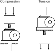
The type of load on a jack, and the way the jack is mounted, affects its load bearing capacity. There are two types of possible jack loads, tension and compression. A jack is under tension when its load pulls the screw away from the jack. It is under compression when the load pushes the lifting screw toward the jack (see diagrams). A jack can be under tension or compression regardless of jack positioning (i.e., vertical, horizontal, upright, or inverted).
When tension loaded, the jack retains full rated capacity. Under compression loads, the screw may not be able to support full capacity. For example, a 2-ton jack with a 15" screw length will be limited to 2293 pounds in compression, about half the jack’s capacity. In compression the load, screw length and jack mounting configuration determine the load capacity of the screw. The examples shown illustrate four common mounting configurations.
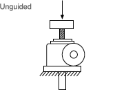
Unguided
If the screw is the only support for the load, it is considered unguided. The screw must be large enough to support the load and prevent buckling. On the Column Loading charts, use the row labeled “unguided” for the allowable lengths for this design. The Column Loading charts are located within the appropriate product sections of the catalog.
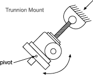
Trunnion Mounting
In a trunnion mounting arrangement, the screw has a pivot on the end and the jack body is mounted on a large pivoting frame, or trunnion. This type of mounting is particularly common in the antenna industry. In practice, the pivot should be as close to the centerline of the internal nut as design permits. This will eliminate moment loads caused by loose threads. Use the “trunnion” row on the Column Loading charts found within the appropriate product sections of the catalog.
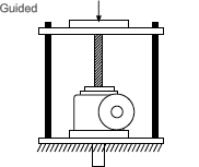
Guided
Guided loading is often termed “fixed-fixed” loading. With guided loading, both ends of the column are rigidly held – the jack body is bolted firmly to a sturdy base, and the load travels on slides, bearings, rollers or other means. The guides should be snug enough to prevent any side load or moment load from reaching the screw. Use the “guided” row on the appropriate column Loading charts.
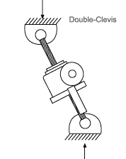
Double-Clevis Mounting
Double-clevis jacks have less load capacity than the other common mounting configurations. A double-clevis jack has pivots or clevises at both ends: one on the screw tip and one on the end of the protection tube. This tends to weaken it as a column by creating eccentric loads on the screw. This eccentricity tends to increase with greater distance and higher loading. For this reason, double-clevis jacks are limited both in capacity and maximum length. Double-clevis mounting differs from trunnion mounting because the pivot is located farther from the jack body. The Column Loading charts do not apply for this mounting. Please consult Joyce for load bearing information.
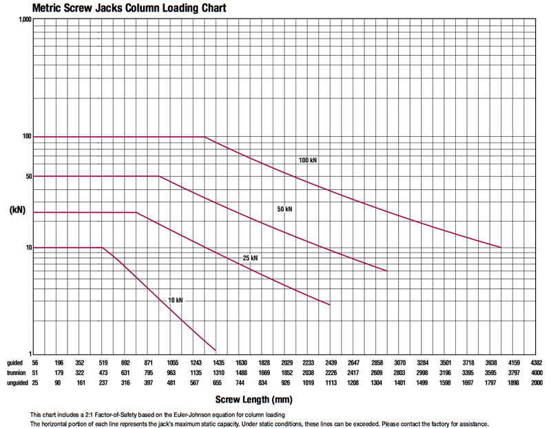
How to use the Column Loading charts:
Note: Charts for machine screw jacks, machine screw ComDRIVEs®, metric screw jacks, ball screw jacks, ball screw ComDRIVEs®, stainless steel jacks, bevel gear jacks, and bevel ball actuators are located within the specific product section of the catalog. These charts only apply to jacks with axial loads. For side loads, offset loads, and horizontal mounting, contact Joyce.
- Determine the type of jack you wish to use and locate that column load chart which is found near the beginning of each product section.
- Determine the proper mounting arrangement for your application. Locate the appropriate row and find the screw length at the bottom of the chart.
- Find the load you need to move (in pounds or kilonewtons) on the left side of the chart.
- Find the point on the chart where the load and length intersect. Choose a jack whose line is on or above this intersection.
- Add the length of the end condition you have chosen and any additional screw extension to the screw length to find the “unbraced” screw length. Verify your selection using the unbraced length.
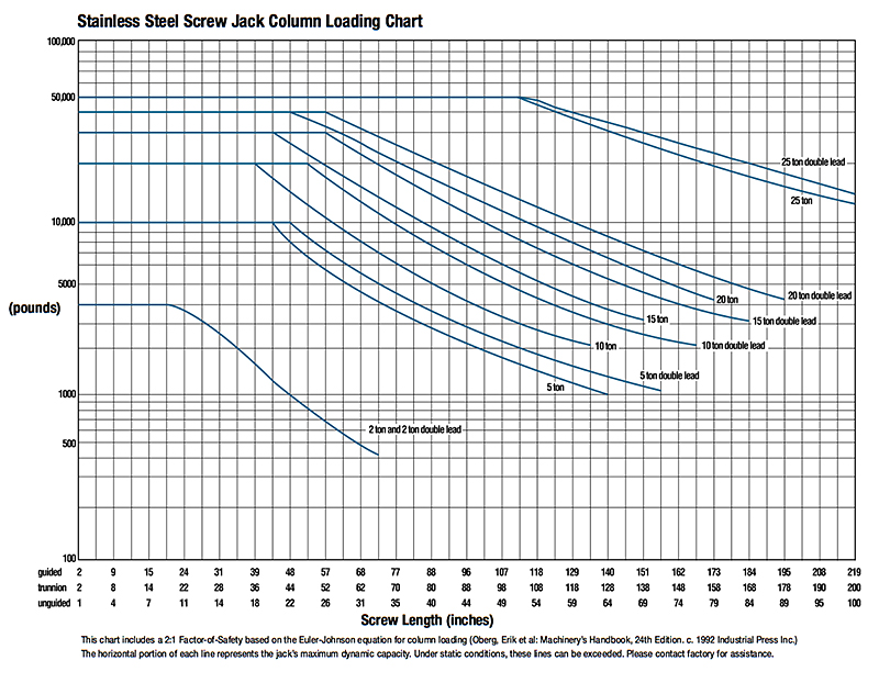
Example:
A jack must lift 5 tons (10,000 pounds) over a distance of 31 inches. The load places the screw in compression. The jack is mounted firmly by its base, and the load is attached toa load pad (Type 2 end) and is not guided.
- In this example, a machine screw jack will be used so locate the Column Loading chart formachine screw jacks on page 24.
- Look at the “unguided” row at the bottom of the machine screw jack Column Loading chart and find the 31" mark.
- From this, the 10-ton double lead jack is selected. Look at the dimensions from the jack body for the Type 2 end for this jack. The Type 2 end adds 2" from the top of the jack to the end of the screw. Thus the total unbraced length of the screw is 31" + 2"= 33".
- Use this new unbraced screw length to verify your selection. In this case, the intersection point still falls below the 10-ton double lead jack line, so this selection is correct.
COLUMN LOAD – CRITICAL FACTORS Instructions for Using Loading Charts Mounting Configurations