FAQs for Jacks
Note: An upright jack mounted upside down is still referred to as an upright jack.
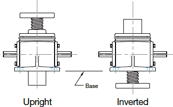
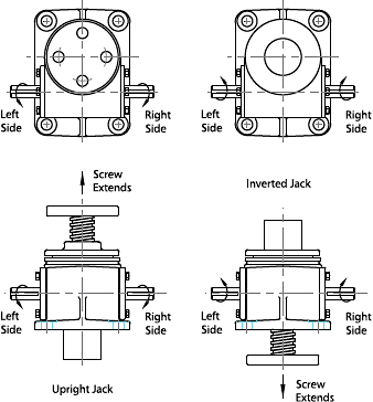
- For an Upright jack:
CCW rotation of right input shaft extending the lifting screw. CW rotation of the left shaft extending lifting screw. - For an Inverted jack:
CW rotation of right input shaft extending lifting screw. CCW rotation of the left shaft extending lifting screw.
Each screw jack and actuator has an inherent number of input shaft turns per inch (TPI) of screw travel. TPI is the result of the jack's gear ratio divided by the lifting screw lead. The TPI can be found on jack specification pages at the beginning of many product sections. A model WJT242 has a TPI of 96. If 350 RPM is applied to the input shaft, the resultant linear speed of travel is 350/96 or 3.65 inches per minute. JAX® Online software automatically calculates travel speeds for you.
All Joyce machine screw jacks and ComDRIVEs®, ball screw jacks and ComDRIVEs®, bevel ball actuators, integrated actuators, and electric cylinders are lubricated with an extreme pressure NLGI grade #1 grease before leaving the factory.
Bevel gear jacks are lubricated with NLGI grade #1 grease and oil. The upper bearing and jackscrew are grease lubricated while the remaining internal components are oil lubricated. They are grease lubricated prior to shipment; however oil must be added to the unit prior to operation.
The following standard end conditions are available on Joyce/Dayton screw jacks:
 Type 1
plain turned end
 Type 2
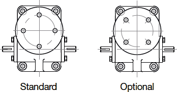
load pad with mounting holes
 Type 3
male threaded end
 Type 4
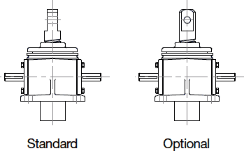
male clevis end
Contact [email protected] for information about custom end conditions.
- Standard clevis mounting position – the hole in the clevis end is parallel with the worm input shaft.
- Optional mounting position – the hole in the clevis end is perpendicular to the worm input shaft.
- Standard load pad mounting position – the holes on the load pad are on the jack centerlines.
- Optional load pad mounting position – the holes on the load pad end straddle the jack centerlines.
Yes. When freedom of movement in two axes is required, a double clevis jack may be specified. Double clevis jacks are always made from upright jacks. Stroke lengths are limited based compression loads. See the chart at the end of the entry. Contact Joyce/Dayton with application details.
- Double clevis jacks incorporate a clevis machined or pinned onto the screw end and also a clevis welded to the protection tube. Screw travel is limited. Contact [email protected] for more information.
- Electric cylinders, integrated actuators, multipurpose actuators, and solar actuators are also available with a clevis on both ends
|
Machine Screw Jack |
Max Load |
Max Rise at full load in Compression |
Reduced Load |
Max Rise at Reduced Load in Compression |
| 1/4-ton | 500 LB | 7.00 Inches | 500 LB | 7.00 Inches |
| 1/2-ton | 1000 LB | 9.00 Inches | 1000 LB | 9.00 Inches |
| 1-ton | 2000 LB | 8.00 Inches | 1500 LB | 10.00 Inches |
| 2-ton | 4000 LB | 12.00 Inches | 3000 LB | 14.00 Inches |
| 3-ton | 6000 LB | 12.00 Inches | 3000 LB | 14.00 Inches |
| 5 ton | 10,000 LB | 17.00 Inches | 6500 LB | 22.00 Inches |
| 10-ton | 20,000 LB | 23.00 Inches | 12,000 LB | 31.00 Inches |
| 15-ton | 30,000 LB | 26.00 Inches | 16,000 LB | 37.00 Inches |
| 20-ton | 40,000 LB | 29.00 Inches | 21,000 LB | 42.00 Inches |
| 25-ton | 50,000 LB | 47.00 Inches | 37,000 LB | 56.00 Inches |
| 30-ton | 60,000 LB | 47.00 inches | 37,000 LB | 56.00 Inches |
| 35-ton | 70,000 LB | 69.00 Inches | 62,000 LB | 74.00 Inches |
| 50-ton | 100,000 LB | 90.00 Inches | 94,000 LB | 93.00 Inches |
Self-locking is a term used to describe jacks that require power to move in either direction. They hold their position when power to the system is off.
A brake is required on the input shaft of any jack that may lower under load (ball screw jacks, WJ500 jacks, double-lead Acme screw jacks, electric cylinders that are more than 30% efficient, and some integrated actuators).
Standard jacks and actuators are not designed for dynamic side loads. The load must be positioned axially. Static side loads are limited. Contact [email protected] for technical assistance.
In machine screw jacks there are two types of backlash: worm to wormgear backlash (typically 8-15° worm rotation), and lifting screw to nut backlash, sometimes called endplay (up to 0.020 inches on new standard jacks). These values are automatically calculated for all products sized in Joyce's free JAX® Online Software for all products. Contact [email protected] for more information.
Yes, screw backlash can be adjusted on translating and keyed style machine screw jacks via one of the following anti-backlash options: standard split-nut design; A90 external nut adjustment; or A95 design. Contact [email protected] for more information.
The deviation from the mathematical lead expressed in inches per foot cumulative.
The level to which products can be serviced in the field varies from product to product. Refer to the product Operation & Maintenance Manuals or contact [email protected] for more information.
Motor options vary among product lines. Customers can use AC 3-phase, AC single-phase, DC motors, international voltage motors and others. Let us know your requirements.
No. Limit switches on multipurpose actuators (MA) are preset at the factory. All other limit switches must be set according to specific directions.
- Shaft-mounted rotary cam limit switches must be set to the required positions during installation.
- Closed height dimensions may increase when boots are added.
- The customer must specify boot collar diameter when ordering bellows boots for KFTN jacks.
- Zippered boots are also available.
- Special boot material is available.
- Horizontal screw applications may require boot guides.
Contact [email protected] for more information.
Stainless steel jacks are inherently corrosion resistant. All exposed surfaces are stainless steel and aluminum bronze. Most other jacks can be modified with special finishes, coatings, and seals. Contact [email protected] with your requirements.
Follower nut assemblies allow customers to gauge the wear on the wormgear screw thread of translating jacks and on the traveling nut screw thread of KFTN jacks. This allows customers to replace the nut before its threads wear too thin to support the design load. These assemblies generally consist of a gear nut or traveling nut pinned to a second nut of dissimilar material. A preset gap separates the two nuts. As the wormgear or traveling nut threads wear, the preset gap narrows. The assembly is replaced when the gap measurement reaches the design limit. Follower nut assemblies are designed for specific applications. Contact [email protected] for more information.
FAQs for EDrive Actuators
Belt tensioning procedures vary from product to product. Please refer to the Service Information section of the website for more specific information.
For the Tac Series, remove the belt housing cover. Loosen the (4) screws to the motor but DO NOT remove them. This will allow you to slide the motor mounting plate toward the actuator body. If both pulleys have flanges, it may be necessary to unbolt the motor in order to remove or install the gear belt. Install the gear belt. Then re-assemble with the correct tension and alignment. Gear belt drives do not need to be tightened to the same extent as other belt drives (i.e. V-belt, Poly-V, Flat belt, etc.). If the gear belt tension is too great, it imposes excessive and unnecessary loading on the bearings.
Lubrication methods and the choice of lubricant may vary from product to product. Please refer to the Service Information section of the website for this information.
The normal temperature range for most EDrive Actuators is -20° F to 175° F. For help specifying actuators which require operation outside of this temperature range contact [email protected] or call (937-294-6261).
B10 life is expressed in total revolutions or inches of travel a system will operate under a rated load. 90% of all systems operated at this rated load will meet or exceed this rating. Although 10% may not reach a million inches, 50% could exceed 5 million inches.
Life under load (B10 life) is predictable; severe load applications can generally be compensated for by providing additional capacity. See our glossary page for other related definitions.
Yes. EDrive offers an Integrated Load Cell option for many of our products. This option combines force measurement with heavy-duty and precise linear motion. It provides a clean, simple, rugged, and economical capability to directly and continuously monitor axial force while simultaneously applying that force. Examples of products with the Load Cell option include HDL and SPL actuators. Eliminator HDL Eliminator SPL For more information contact [email protected] or call (937-294-6261).
IP69K indicates the highest rating available on the internationally recognized scale for classifying ingress protection against dust and high-temperature, high-pressure liquids. Products with IP69K protection are ideal for use in industries such as Food Processing and Medical Equipment applications where equipment must routinely withstand rigorous washdown procedures.
IP = Ingress Protection
6 = No ingress from dust and dirt
9K = No ingress from high-pressure, high-temperature spray from close proximity and from various angles.
FAQs for Customer Service
Use our on-line RMA form and we will quickly send you the information you need to return the unit to us. For more information contact [email protected] or call (937-294-6261).
Distributors from all over North America provide EDrive products. Your local Sales Rep will be able to direct you to distributors in your area or contact [email protected] or call (937-294-6261).
Please contact your local sales rep or contact [email protected] or call (937-294-6261).
Standard warranty information is included in our Sales Terms & Conditions. For more information contact contact [email protected] or call (937-294-6261).
We offer customers several options to help size actuators. Use our website Product Selector to narrow your search then send your request to us using the RFQ form. Register on the site to gain access to our 2D/3D modeling software that allows you to search part numbers and select options. Contact our Customer Service Reps or Application Engineers for personal service. We are here to help you. Let us know how we can best serve you. For more information contact contact [email protected] or call (937-294-6261).
We are located at 1621 N Meridian St, Portland, IN 47371.