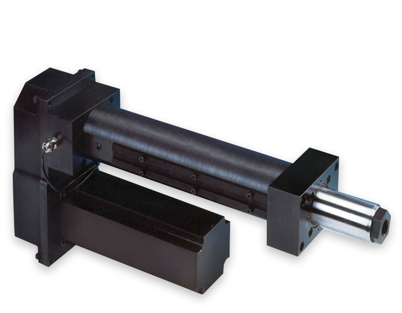
Eliminator HDL with Integrated Load Cell ™
Eliminator HDL with Integrated Load Cell ™
Key Features:
- “Measure while you Press” integrated load cell design
- Conforms to latest standard ASTM E4 for testing machines
- Rated thrust up to 40,000 lbf
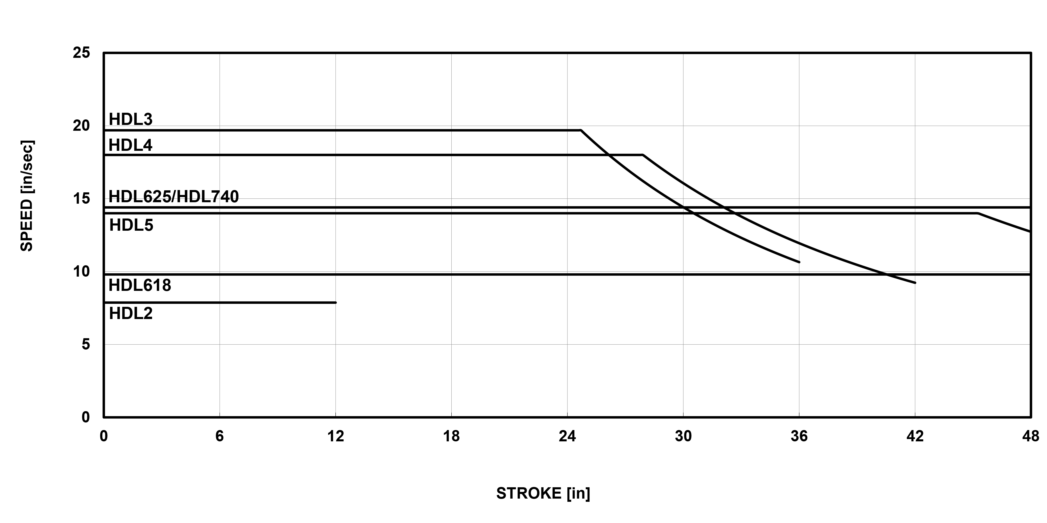
- High velocity up to 20 in/sec, stroke up to 48 inches
2D/3D Drawings
Login to access the 2D/3D Drawings
Charts
Product Media
Available Products
Eliminator HD + Integrated Load Cell
The Eliminator HDL combines all the precision features of the HD series with the additional benefit of an integrated load cell, providing continuous and accurate measurement of applied thrust. This heavy-duty, rugged linear actuator provides a clean, simple, and economical solution for your high-speed precision thrust applications.
Login to access the 2D/3D Drawings
English
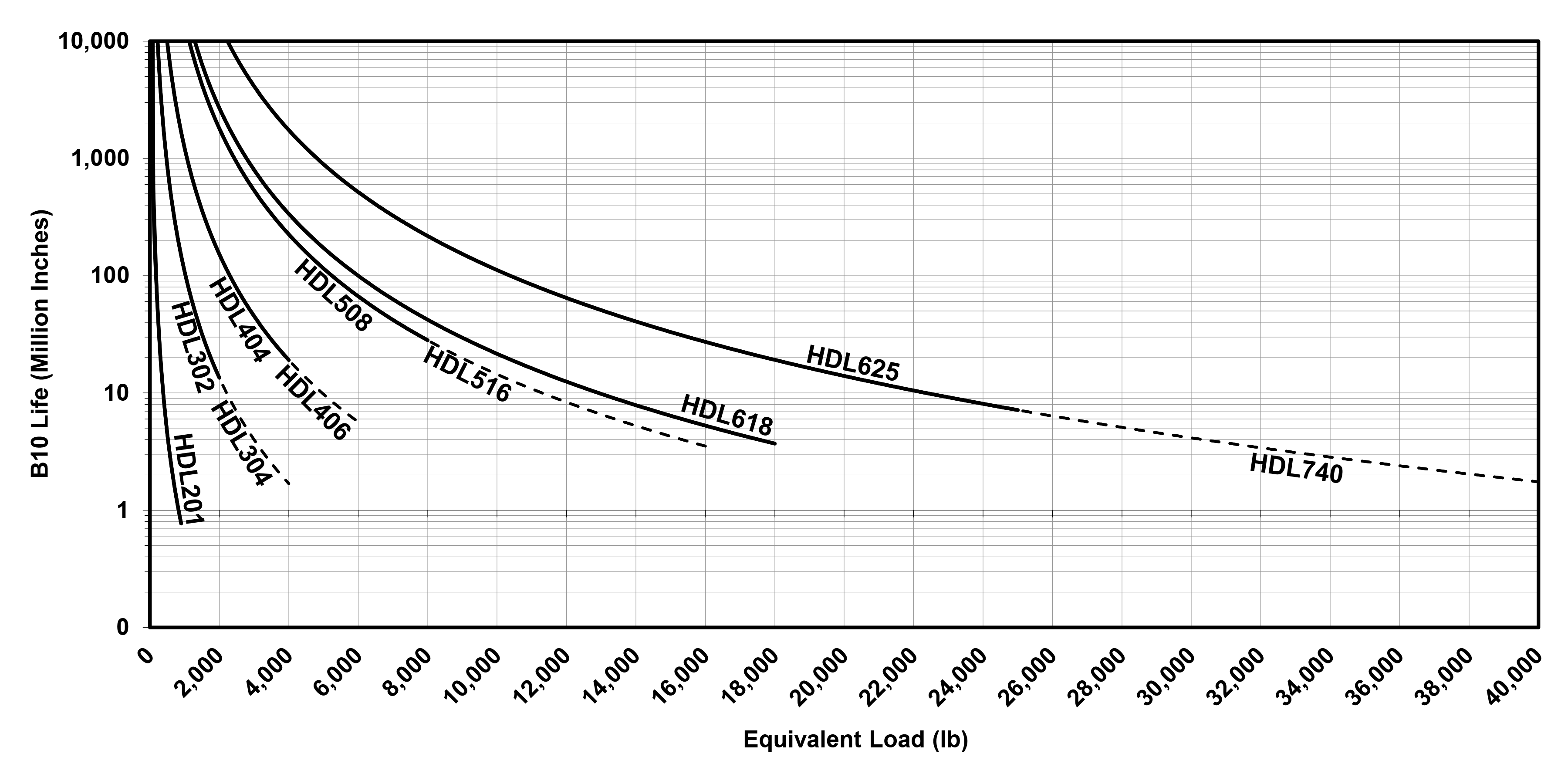
| Models | Rated Thrust | Max. Velocity1 | Max. Stroke2 | Frame Size | Screw Lead | Max. Screw Speed1 | Max. Torque At Screw | Dynamic Capacity Per Million Revs | Dynamic Capacity Per Million Inches | Max. Motor Or Gearhead Frame Supported2 | Inertia 1:1 Zero Stroke3 | Inertia 1:1 Per Inch Of Stroke3 | Inertia 2:1 Zero Stroke3 | Inertia 2:1 Per Inch Of Stroke3 | Inertia Inline Zero Stroke3 | Inertia Inline Per Inch Of Stroke3 | Weight "U" Mount Zero Stroke4 | Weight "L" Mount Zero Stroke4 | Weight Per Inch Of Stroke4 |
|---|---|---|---|---|---|---|---|---|---|---|---|---|---|---|---|---|---|---|---|
| Units | lbf | in/s | in | in | mm | RPM | in-lbf | lbf | lbf | in | lb-in² | lb-in² | lb-in² | lb-in² | lb-in² | lb-in² | lb | lb | lb |
| HDL201 | 1000 | 8.00 | 12 | 2.00 | 4 | 3,048 | 28 | 1,529 | 825 | 2.75 | 0.51 | 0.0031 | 0.27 | 0.0008 | 0.04 | 0.0031 | 8 | 6 | 1 |
| HDL302 | 2,000 | 20.0 | 36 | 3.00 | 10 | 3,048 | 139 | 6,490 | 4,760 | 4.25 | 4.31 | 0.0212 | 1.64 | 0.0053 | 0.34 | 0.0212 | 29 | 22 | 1 |
| HDL304 | 4,000 | 20.0 | 36 | 3.00 | 10 | 3,048 | 278 | 6,490 | 4,760 | 4.25 | 4.87 | 0.0212 | 1.46 | 0.0053 | 0.38 | 0.0212 | 29 | 22 | 1 |
| HDL404 | 4,000 | 18.0 | 42 | 4.00 | 10 | 2,743 | 278 | 14,580 | 10,690 | 5.75 | 23.24 | 0.0457 | 4.11 | 0.0114 | 1.99 | 0.0457 | 63 | 49 | 2 |
| HDL406 | 6,000 | 18.0 | 42 | 4.00 | 10 | 2,743 | 418 | 14,580 | 10,690 | 5.75 | 23.24 | 0.0457 | 4.11 | 0.0114 | 1.99 | 0.0457 | 63 | 49 | 2 |
| HDL508 | 8,000 | 14.0 | 48 | 5.00 | 12 | 1,778 | 668 | 31,250 | 24,340 | 8.00 | 139.27 | 0.2688 | 22.66 | 0.0672 | 5.92 | 0.2688 | 155 | 105 | 3 |
| HDL516 | 16,000 | 14.0 | 48 | 5.00 | 12 | 1,778 | 1,337 | 31,250 | 24,340 | 8.00 | 139.36 | 0.2688 | 22.68 | 0.0672 | 6.00 | 0.2688 | 155 | 105 | 3 |
| HDL618 | 18,000 | 9.8 | 48 | 6.00 | 12 | 1,245 | 1,504 | 35,750 | 27,840 | 8.00 | 281.96 | 0.7361 | 43.91 | 0.1840 | 12.31 | 0.7361 | 207 | 152 | 6 |
| HDL625 | 25,000 | 14.4 | 48 | 6.00 | 20 | 1,097 | 3,481 | 52,150 | 48,160 | 8.00 | 295.02 | 1.8713 | 47.17 | 0.4678 | 25.37 | 1.8713 | 214 | 158 | 6 |
| HDL740 | 40,000 | 14.4 | 48 | 7.00 | 20 | 1,097 | 5,575 | 52,150 | 48,160 | 10.875 | 401.8526 | 1.8707 | 64.8706 | 0.4677 | 96.2948 | 1.8707 | 373 | 318 | 7.41 |
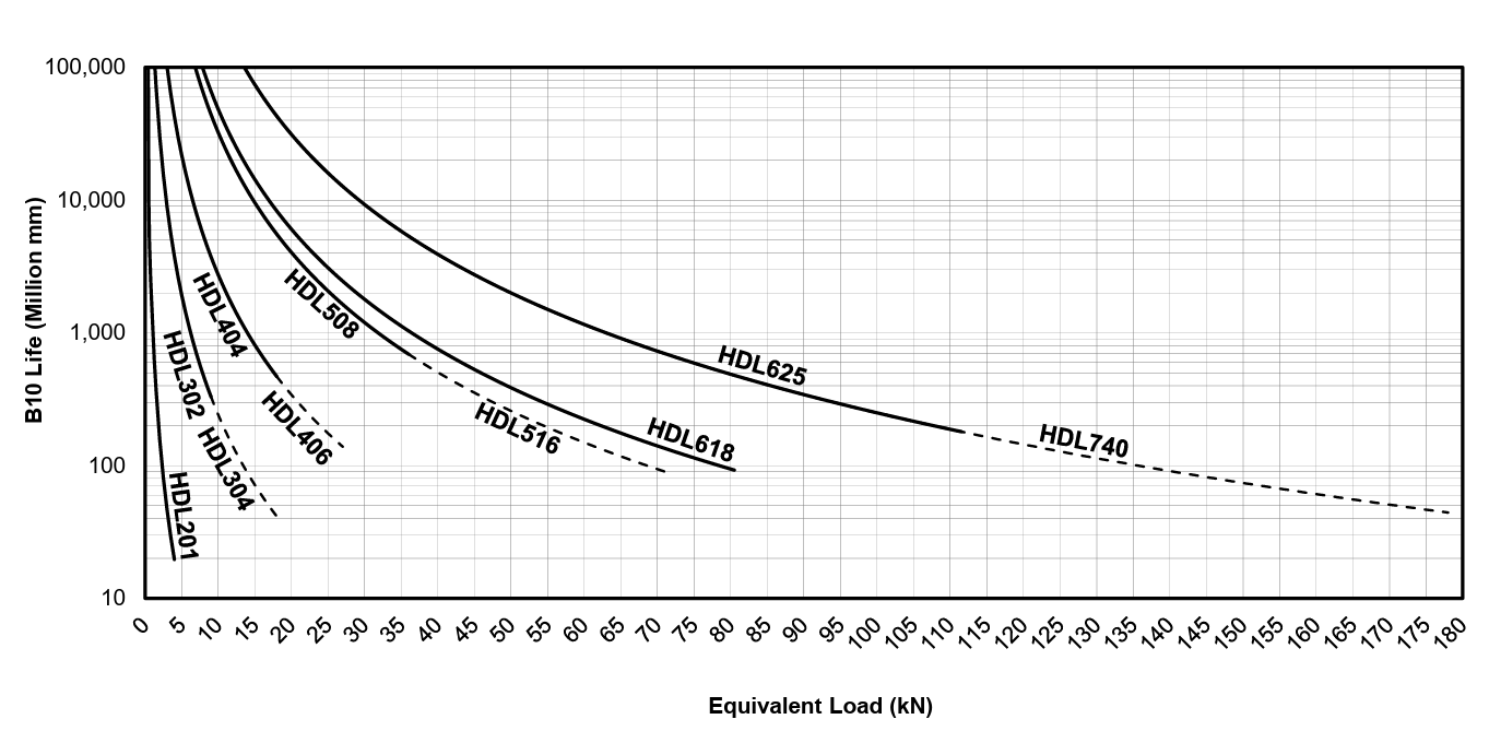
Metric
| Models | Rated Thrust | Max. Velocity1 | Max. Stroke2 | Frame Size | Screw Lead | Max. Screw Speed1 | Max. Torque At Screw | Dynamic Capacity Per Million Revs | Dynamic Capacity Per Million Inches | Max. Motor Or Gearhead Frame Supported2 | Inertia 1:1 Zero Stroke3 | Inertia 1:1 Per Inch Of Stroke3 | Inertia 2:1 Zero Stroke3 | Inertia 2:1 Per Inch Of Stroke3 | Inertia Inline Zero Stroke3 | Inertia Inline Per Inch Of Stroke3 | Weight "U" Mount Zero Stroke4 | Weight "L" Mount Zero Stroke4 | Weight Per Inch Of Stroke4 |
|---|---|---|---|---|---|---|---|---|---|---|---|---|---|---|---|---|---|---|---|
| Units | kN | mm/s | mm | mm | mm | RPM | Nm | kN | kN | mm | kg-m² (10⁻⁶) | kg-m² (10⁻⁶) | kg-m² (10⁻⁶) | kg-m² (10⁻⁶) | kg-m² (10⁻⁶) | kg-m² (10⁻⁶) | kg | kg | kg |
| HDL201 | 4.45 | 203 | 305 | 50.8 | 4 | 3,048 | 3.1 | 6.80 | 3.67 | 70 | 148.33 | 0.8952 | 78.75 | 0.2238 | 10.91 | 0.8952 | 4 | 3 | 0.40 |
| HDL302 | 8.90 | 508 | 914 | 76.2 | 10 | 3,048 | 15.7 | 28.87 | 21.17 | 108 | 1,648.16 | 5.9369 | 477.87 | 1.4842 | 95.60 | 5.9369 | 13 | 10 | 0.60 |
| HDL304 | 17.79 | 508 | 914 | 76.2 | 10 | 3,048 | 31.5 | 28.87 | 21.17 | 108 | 1,420.65 | 5.9305 | 427.18 | 1.4826 | 107.02 | 5.9305 | 13 | 10 | 0.60 |
| HDL404 | 17.79 | 457 | 1,067 | 101.6 | 10 | 2,743 | 31.5 | 64.86 | 47.55 | 146 | 6,793.93 | 12.9806 | 1,202.31 | 3.2452 | 574.03 | 12.9806 | 28 | 22 | 1.02 |
| HDL406 | 26.69 | 457 | 1,067 | 101.6 | 10 | 2,743 | 47.2 | 64.86 | 47.55 | 146 | 6,793.93 | 12.9806 | 1,202.31 | 3.2452 | 574.03 | 12.9806 | 28 | 22 | 1.02 |
| HDL508 | 35.59 | 356 | 1,219 | 127.0 | 12 | 1,778 | 75.5 | 139.01 | 108.27 | 203 | 40,729.48 | 77.4238 | 6,624.64 | 19.3559 | 1,703.82 | 77.4238 | 70 | 47 | 1.54 |
| HDL516 | 71.17 | 356 | 1,219 | 127.0 | 12 | 1,778 | 151.0 | 139.01 | 108.27 | 203 | 40,754.98 | 77.4238 | 6,631.01 | 19.3559 | 1,729.32 | 77.4238 | 70 | 47 | 1.54 |
| HDL618 | 80.07 | 249 | 1,219 | 152.4 | 12 | 1,245 | 169.9 | 159.02 | 123.84 | 203 | 82,476.19 | 213.6915 | 12,840.60 | 53.4229 | 3,566.01 | 213.6915 | 94 | 69 | 2.49 |
| HDL625 | 111.21 | 366 | 1,219 | 152.4 | 20 | 1,097 | 393.3 | 231.97 | 214.23 | 203 | 86,146.23 | 542.1018 | 13,758.11 | 135.5254 | 7,236.04 | 542.1018 | 97 | 72 | 2.49 |
| HDL740 | 177.93 | 366 | 1,219 | 177.8 | 20 | 1,097 | 630 | 231.97 | 214.23 | 276 | 117598.4151 | 547.4429 | 18983.7760 | 136.8680 | 28179.7750 | 547.4429 | 169 | 144 | 3.36 |
1. Maximum velocity and maximum screw speed may not be achievable at maximum stroke.
2. Larger Motor or Gearhead Frames and longer stroke lengths are available upon request.
3. All inertia values are at the input shaft and are representative of typical pulleys, bushings, couplers, etc. Actual values may vary due to motor selection.
4. Weight values are for reference only and vary depending on configuration.
"U" Parallel offset configuration
"L" Inline configuration