Machine Screw comDRIVEs
About Machine Screw ComDRIVEs
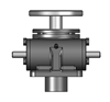
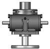
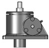
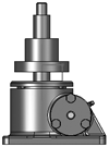
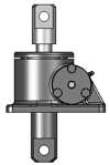
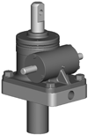
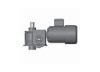
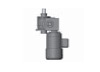
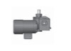
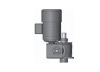
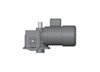
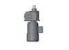
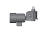
Joyce Machine Screw ComDRIVEs combine a machine screw jack, motor and gear reducer into a single compact unit. Motorized ComDRIVEs are available in 2-ton through 30-ton capacities with travel speeds up to 35.1 inches per minute. ComDRIVEs with single lead screws (CD) are self-locking; those with double lead screws (DCD) may require a brake to hold position.
- ComDRIVEs can power an entire jacking system
- Reduce the number of components that must be specified
- Simplify designs
- Reduce installation costs with only a single plate needed to mount the jack body
- Reduce the number of couplings and shafts required in multi-jack systems
- Standard 230/460 volt, 3-phase, 60 hertz motor included
- Custom finishes available
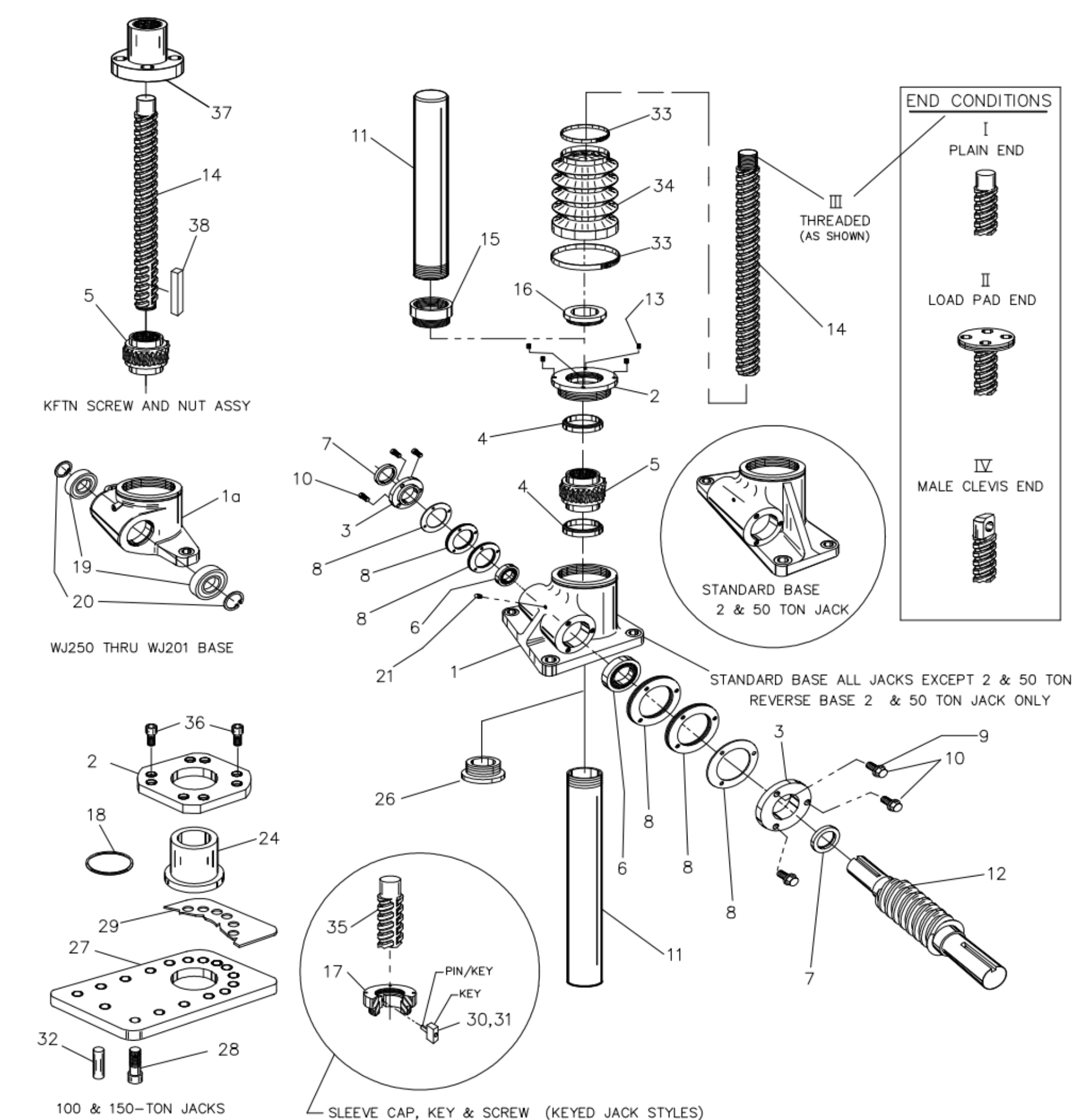
Parts list and exploded views are included in the O&M Manual. A serial number is attached to the product housing.
Product Media

Available Models
Jack Material Notes:
- Ductile iron jack housing
- Lifting screw, cold drawn steel (CDS)
- Input shaft (worm), CDS
- Aluminum bronze traveling nut (KFTN)
Motor Notes:
- 230/460 Volt, 3 phase, 60-hertz motor is standard
Sample Part Number:
Click on the part number to reveal additional informaton about jack designs and shaft codes.
Model Number
| 2-Ton | 3-Ton | 5-Ton | 10-Ton | 15-Ton | 20-Ton | 25-Ton | 30-Ton |
|---|---|---|---|---|---|---|---|
| CD62 CD122 CD242 |
CD63 CD123 CD243 |
CD65 CD125 CD245 |
CD810 CD2410 |
CD815 CD2415 |
CD820 CD2420 |
CD1125 CD3225 |
CD1130 CD3230 |
| DCD62* DCD122* DCD242* |
DCD63* DCD123* DCD243* |
DCD65* DCD125* DCD245* |
DCD810* DCD2410* |
DCD815* DCD2415* |
DCD820* DCD2420* |
DCD1125* DCD3225* |
DCD1130* DCD3230* |
Important Note: *Not self-locking, may lower under load. Brake motors or external locking systems are recommended.
DCD: Double lead screw.
(For 25:1 ratio, contact Joyce/Dayton.)
Jack Configuration
 |
 |
|
U=Upright |
I=Inverted |
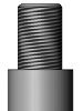
End Conditions
 |
 |
 |
 |
|
1=T1 |
2=T2 |
3=T3 |
4=T4 |
Jack Designs
 |
 |
 |
 |
|
|
S=Translating |
K=Keyed for Non Rotation |
N=Traveling Nut |
D=Double Clevis |
R=KFTN Trunnion* |
* Standard trunnion mounts available on 2-ton through 20-ton jacks.
ComDRIVE® Rise
Rise is travel expressed in inches and not the actual screw length. When companion jacks are ordered with the ComDRIVE®, their screws are lengthened to match the ComDRIVE®.
Left Side Shaft Code |
Right Side Shaft Code |
|
XXXX=Remove |
XXXX=Remove |
Optional Shaft Codes
Screw Stops and Boots
Extending and retracting screw stops are standard on ComDRIVEs. When boots are added to ComDRIVEs, the closed height of the unit may be increased.
Mechanical Counters
CNT0=0.001" Increments
Note: Contact Joyce/Dayton for availability and options.
Geared Potentiometers
POTA=0-10V (IP65)
POTB=4-20MA (IP65)
POTC=0-10V w/2 switches*
POTD=4-20MA w/2 switches*
*Optional IP65 rating available
Encoders and Electronic Limit Switches
ENCX=Encoder
ELS2=2 Position Electronic Switch
ELS4=4 Position Electronic Switch
ELS6=6 Position Electronic Switch
Motor for Systems and Direct Drives
- All standard motors are 3-phase, 208-230/460 VAC or 230/460 VAC. Other motor options are available. Specify the appropriate motor size from the chart on the right.
- Refer to the "Additional Options" chart on the preceding page as needed.
- Brake motors (M2) are recommended for jacks that are not self-locking, and jacks with double lead screws.
- If the motor frequency will be varied to provide a "soft" start an inverter duty motor may be required.
ComDRIVE Reducers
Ordering Example:
P2 (Mounting Positions) A (Ratio) C (Motor code from chart above)
| Mounting Positions | ||||
|---|---|---|---|---|
| Code | P1 | P2 | P3 | P4 |
| Left Side Shaft Options |
 |
 |
 |
 |
| Right Side Shaft Options |
 |
 |
 |
 |
| Ratio |
|---|
| 5:1 Code A |
| 7.5:1 Code B |
| 10:1 Code C |
| Motors | |
|---|---|
| Size | Code |
| 1/4 HP | K |
| 1/3 HP | A |
| 1/2 HP | B |
| 3/4 HP | C |
| 1 HP | D |
| 1-1/2 HP | E |
| 2 HP | F |
| 3 HP | L |
| 5 HP | G |
| 7-1/2 HP | H |
| 10 HP | I |
| 15 HP | J |
All standard motors are 3-phase, 208-230/460 VAC or 230/460 VAC. Other motor options are available including international voltages, and single phase AC. Specify the appropriate motor size from the chart above. Refer to the “Additional Options” chart on the preceding page as needed. Brake motors are required for ball screw ComDRIVEs®. Contact Joyce/Dayton for other options.
Mechanical Limit Switches
Ordering Example:
LA (Models) 1(Number of DPDT Switches) 3(Available Positions)
| Model | Code | Available Positions | |||||||||
|---|---|---|---|---|---|---|---|---|---|---|---|
| LS7-402 | LI |
Number of DPDT Switches NOTE: Will always be 0 for LS7 models |
1 | 2* | 3 | 4 | 5 | 6* | 7 | 8 | |
| LS8-402 | LA | Left Side Shaft Options |  |
 |
 |
 |
 |
 |
 |
 |
|
| LS8-504 | LB | ||||||||||
| LS9-502 | LC | ||||||||||
| LS9-503 | LD | Right Side Shaft Options |  |
 |
 |
 |
 |
 |
 |
 |
|
| LS9-504 | LE | ||||||||||
| LS9-505 | LF | ||||||||||
| LS9-506 | LG |
These positions are not standard. Contact Joyce/Dayton with your requirements. |
|||||||||
| LS9-507 | LH | ||||||||||
Additional Options
- X=Standard Jack, no additional options
- S=Additional Specification Required (comment as necessary)
Anti-Backlash
- A=Split Nut
- A90=A90 Design
- A95=A95 Design
Protective Boots
- B=Protective Boot
- D=Dual Protective Boot
Finishes
- F1=Do Not Paint
- F2=Epoxy Paint
- F3=Outdoor Paint Process
Motor Options
- M1=Less Motor
- M2=Brake Motor
- M3=Single Phase Motor (120VAC)
- M4=50Hz Motor
Grease/Seals
- H1=High Temperature Operation
- H2=Food Grade
Screw Stops
- ST0=Extending
- ST1=Retracting
- ST2=Both
- Specify as many options as needed
| 2 Ton Model Number | CD62 | CD122 | CD242 | DCD62 | DCD122 | DCD242 | ||||||||||
|---|---|---|---|---|---|---|---|---|---|---|---|---|---|---|---|---|
| Reducer Ratio | 5 | 7 1/2 | 10 | 5 | 7 1/2 | 5 | 7 1/2 | 10 | 5 | 7 1/2 | 10 | 7 1/2 | 5 | 7 1/2 | 10 | |
| Travel Speed IPM | 13.88 | 9.50 | 7.04 | 6.94 | 4.75 | 3.47 | 2.38 | 1.76 | 27.75 | 19.00 | 14.08 | 9.50 | 6.94 | 4.75 | 3.52 | |
| Lifting Capacity (Lbs.) |
1/3 HP | 1,865 | 2,650 | 3,500 | 3,350 | 4,000 | 4,000 | 4,000 | 4,000 | 1,300 | 1,850 | 2,450 | 3,300 | 3,830 | 4,000 | 4,000 |
| 1/2 HP | 2,875 | 4,000 | 4,000 | 4,000 | 2,000 | 2,825 | 3,720 | 4,000 | 4,000 | |||||||
| 3/4 HP | 4,000 | 3,060 | 4,000 | |||||||||||||
Important Note: DCD models may lower under load. Brake motors or external locking systems are recommended.