Electric Cylinders
Electric Cylinders
Also called an electric actuator, an electric cylinder is a device that uses electricity to create linear motion for numerous applications. Industries that depend on automation, such as manufacturing, pharmaceutical, and product packaging, use electric cylinders to push or pull something in a straight line.
Joyce/Dayton Corp. is a premier manufacturer of electric cylinders, and we have a long history of designing high-quality motion control solutions for modern industries worldwide. Read on to learn more about the common types of electric cylinders, their applications, and their benefits.
Types of Electric Cylinders
An electric cylinder is a kind of actuator used in industrial automation. It converts electrical energy into linear motion with high thrust force. Regardless of the type, the key components of an electric cylinder are a housing, motor, screw or rotor, control system, and feedback system.
These are the main types of electric cylinders.
Linear Actuators
The most common type of electric cylinder, a linear actuator is similar in form to pneumatic and hydraulic cylinders. To operate, a motor drives a lead screw and converts its rotary motion into linear motion for the piston rod. In automobiles, for example, linear actuators help to open trunks, sunroofs, and doors.
Guided Cylinders
Guided cylinders combine the power of a linear actuator with the precision of a slide. They offer superior stability and accuracy for demanding tasks that require strict alignment.
How to Size an Electric Cylinder Actuator
Electric Cylinders are sized based on their static thrust capacity, but selection of the best model and configuration of electric cylinders for specific applications requires further consideration.
Joyce’s complementary JAX® Online software makes it easy to size a single unit of a complete system. Contact one of our Application Engineers today.
First, consider the mounting orientation and static load. Vertical mounting and operation permit a longer maximum rise (stroke) than horizontal mounting and operation of electric cylinders. For a given thrust capacity, maximum rise values may differ based on the screw type and diameter. Be sure to check Quick Reference pages.
Consider the DYNAMIC load. The speed at which the load will be moved is a limiting factor. Quick reference pages are arranged from slowest to the fastest operation of acme screw (ECA) cylinders and then ballscrew (ECB) cylinders. Scan down the list to the travel speed you need and then check the horsepower requirements for the load you will be moving.
How frequently will the Electric Cylinder need to move the load? Electric Cylinders with Acme screws (ECA) have a calculated allowable continuous travel that limits duty cycle. Use JAX® to determine this value.
How long will the Electric Cylinder be in service? Electric Cylinders with ballscrews (ECB) have a calculated ball nut life, expressed in inches of travel, which can be used to estimate the life of the unit. Use JAX® to determine this value.
Joyce/Dayton offers motor controls ranging from simple motor starters to complex positioning systems and custom controls. Every system that is powered by an electric motor requires a control system. At Joyce, we know that choosing the best option can sometimes be a challenge. That’s why our Engineers are available to help you through the process.
Applications for Electric Cylinders
Electric cylinders are crucial in a variety of industries:
- Factory Automation: From pick-and-place robots to material handling equipment, electric cylinders play an important role in factory automation. They provide precise movement in packaging processes and assembly lines.
- Medical: Electric cylinders are ideal for the medical industry because they can be easily cleaned and controlled for operating surgical tools, powering diagnostic equipment, and adjusting patient beds.
- Food & Beverage: The food and beverage industry uses electric cylinders to handle jobs in high-hygiene environments such as dispensing ingredients and packaging finished products.
- Electronics: Precise positioning capabilities make electric cylinders fit for tasks like component placing and testing in electronics manufacturing.
Benefits of Electric Cylinders
Compared to other types of motion control devices, electric actuators offer many advantages for the above applications:
- Precise Control: Electric cylinders deliver exceptional control over force, position, and speed, creating accurate and smooth motion. They excel in tasks that require exact positioning with high repeatability.
- Efficiency: Electric cylinders do not rely on compressed air systems, reducing energy consumption.
- Quiet Operation: Because no air compressors are necessary, electric cylinders reduce noise pollution and operate more quietly than hydraulic and pneumatic actuators. This makes electric cylinders ideal for noise-sensitive applications.
- Versatility: With different stroke lengths, motor types, and mounting options, electric cylinders can adapt to a wide range of applications.
- Ease of Use: With programmable controllers and microprocessors, electric cylinders are easier to integrate into existing systems than hydraulic or pneumatic cylinders.
- Customizable: Electric cylinders are easier to customize to specific application requirements, such as those for speed, stroke length, and applied force.
- Easy Diagnostics and Maintenance: With built-in feedback capabilities, electric cylinders allow technicians to keep track of real-time operation and initiate predictive maintenance as needed. This responsiveness minimizes downtime and improves overall system reliability.
Electric Cylinders from Joyce/Dayton
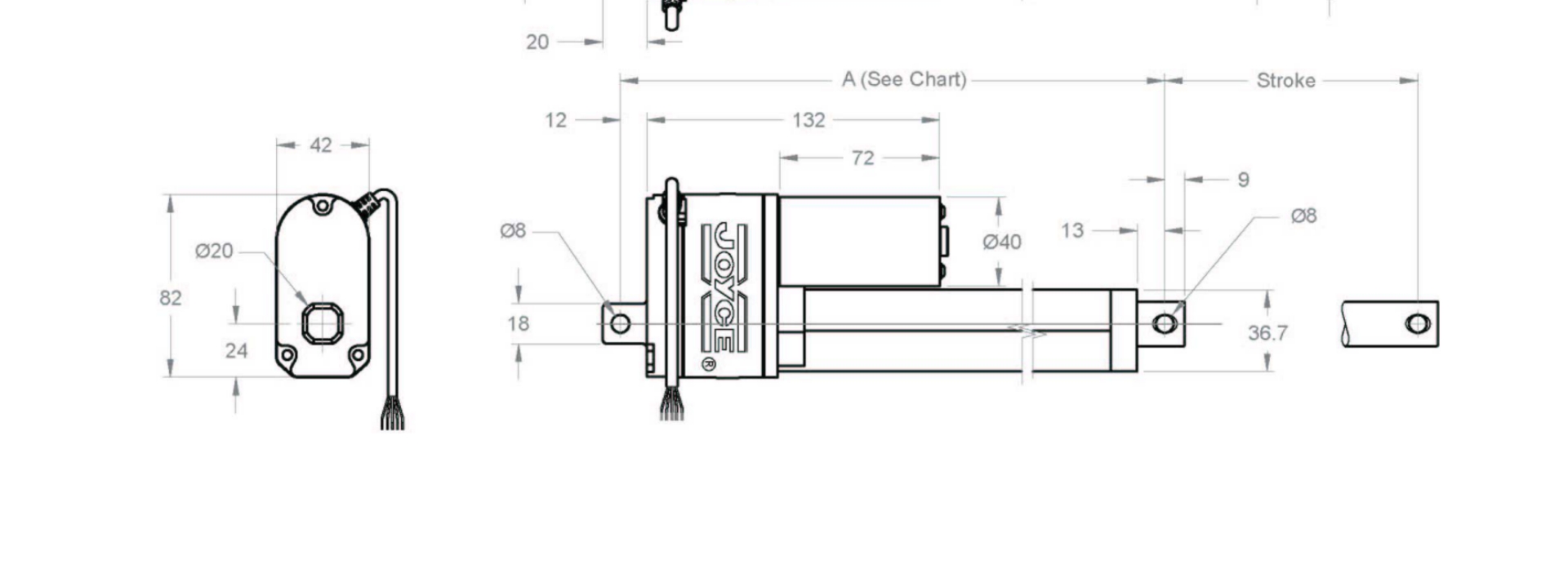
Electric actuators can be tailored to your specific application’s requirements, offering precision, versatility, and efficiency for your motion control needs. At Joyce/Dayton, our electric cylinder actuators can precisely lift and position loads weighing up to 20 tons, reach speeds up to 546 in./min., and raise loads to heights of up to 100 in. Our electric cylinders are ideal for industrial automation applications where the lifting screw mechanism must be protected while operating reliably.
Request a quote to get started with your custom electric actuator solution.
Product Media
Available Models
Click To Expand

Items to consider when selecting motors and mounting configurations:
Use Quick Reference Charts determine the motor horsepower and gear reduction required to reach your target speed. For example, slow travel of just a few inches per minute will require a high ratio electric cylinder paired with a 10:1 ratio external gear reducer. While fast travel up to 546 inches per minute will require a low ratio electric cylinder paired with a direct drive motor.
- Standard model Electric Cylinders are purchased without a motor or external gear reducer.
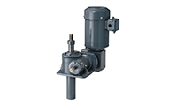
- Direct Drive models have the motor mounted directly to the input shaft of the Electric Cylinder. The motor extends at a 90 degree angle from eh electric cylinder.
- ComDRIVE models have mounted external gear reducers and motors. The combination of internal and external gear reduction is specified and it accounts for output speed of the specific electric cylinder.
NOTE: Brake motors must be specified for all ballscrews Electric Cylinders (ECB).and for any acme Screw Electric Cylinder (ECA) with an efficiency ratio greater than or equal to 30%.
Smaller Capacity Linear Actuators are available from Joyce:
- Multipurpose Actuators - 1600 lb max. capacity, both AC and DC available, speeds to 96 in./min.
- Integrated Actuators - 2000 lb. max. Capacity, AC, speeds to 345 in./min.
Customization and Special Finishes:
Joyce can customize your Electric Cylinders to meet your requirements.
- Premium external finishes
- Proprietary Outdoor paint process resists corrosive elements and works well in harsh environments.
ComDRIVE Options
- Special reducer ratios available
- Special mounting positions available
- Special motor adapters available
- Mount limit switch to gear reducers
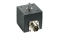
Encoders
- Standard 200 or 1024 PPR
- Quadrature wave form
- Stainless steel encoder
- Absolute encoder
- Encoders
Finishes
- Enamel finish (standard)
- Epoxy finish
- STEEL IT® epoxy
- Outdoor paint process
- Custom finishes available
- Anodized (250-lb to 1-ton)
- Nickel, Xylan®, Armoloy®
- Finishes
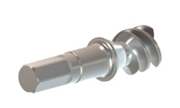
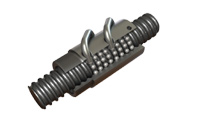
Input Shaft (worm)
- Square or hex to fit tool
- Special lengths
- 17-4 stainless steel available
- Metric diameters available
- One side can be cut off
- Other modifications available
- Input shaft cover available
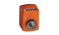
Limit Switches
- Rotary cam (2-4 switches)
- SPDT standard
- DPDT available
- Explosion proof available
- Limit Switches

Lubrication
- Standard grease temperature range (40°F to 220°F)
- Low temperature option
- High temperature option
- Food grade option
Motor Mounts
- NEMA mounts available on 2-ton to 20-ton wormgear jacks and electric cylinders
- NEMA mounts included on integrated actuators
- Servo motor mounts available on 2-ton to 10-ton jacks and electric cylinders, special mounts available
- Custom mounts available
- Motor Mounts and Stock Motors
Oversized Ball Bearings
- Available for ball screw jacks
- Limits screw backlash to 0.003"
Potentiometers
- 0-10V (POTA)
- 4-20mA (POTB)
- 0-10V with limit switches (POTC)
- 4-20mA with limit switches(POTD)
- IP65
- Potentiometers
Sample Part Number:
Click on the part number to reveal additional informaton about jack designs and shaft codes.
Model Number
| 2.5-Ton ACME Screw |
2.5-Ton Ball Screw |
3-Ton ACME Screw |
3-Ton Ball Screw |
5-Ton ACME Screw |
5-Ton Ball Screw |
10-Ton ACME Screw |
10-Ton Ball Screw |
20-Ton ACME Screw |
20-Ton Ball Screw |
|---|---|---|---|---|---|---|---|---|---|
| ECAL242.5
ECAH62.5 |
ECBL62.5 ECBL122.5 ECBL242.5 ECBM62.5 ECBH62.5 |
ECAL63 ECAL123 ECAL243 |
ECBL63 ECBL123 ECBL243 ECBH63 |
ECAL65 ECAL245 ECAM65 ECAH65 |
ECBL65 ECBL125 ECBL245 ECBM65 ECBH65 |
ECAL810 ECAL2410 ECAM810 ECAH810 |
ECBL810 ECBL2410 ECBM810 ECBH810 |
ECAL820 ECAL2420 ECAM820 ECAH820 |
ECBL820 ECBL2420 |
Important Note: Electric Cylinders that are ≥ 30% efficient may lower under load. Brake motors or external locking systems are required.
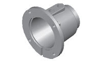
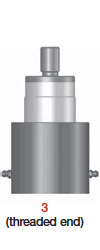
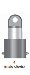
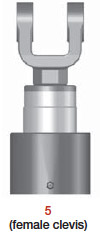
Tube End Conditions
 |
 |
 |
 |
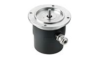
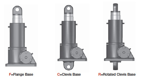
Base Designs
 |
Cylinder Rise
Rise is travel expressed in inches and not the actual tube length. The allowable travel for each unit is listed in the Quick Reference section. Allowable lengths differ for vertical and horizontal mounting.
Left Side Shaft Code |
Right Side Shaft Code |
|
XXXX=Remove |
XXXX=Remove |
Optional Shaft Codes
Screw Stops and Boots
Screw stops are optional on machine screw jacks. When specified, the closed height of the jack and/or the protection tube length may be increased. When boots are added to machine screw jacks, the closed height of the jack may be increased.
Mechanical Counters
CNT0=0.001" Increments
Note: Contact Joyce/Dayton for availability and options.
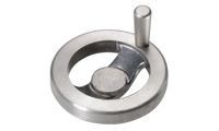
Hand Wheels
HW04=4" dia
HW06=6" dia
HW08=8" dia
HW10=10" dia
HW12=12" dia
Not recommended for cylinders that are ≥ 30% efficient.
Geared Potentiometers
POTA=0-10V (IP65)
POTB=4-20MA (IP65)
POTC=0-10V w/2 switches*
POTD=4-20MA w/2 switches*
*Optional IP65 rating available
Encoders and Electronic Liit Switches
ENCX=Encoder
ELS2=2 Position Electronic Switch
ELS4=4 Position Electronic Switch
ELS6=6 Position Electronic Switch
| ComDrive Reducers | |||||
|---|---|---|---|---|---|
| Ordering Example: P2 (Moutning Positions) A (Ratio) C (Motor code from chart below) | |||||
| Mounting Positions | Ratio | ||||
| Code | P1 | P2 | P3 | P4 |
5:1 7.5:1 10:1 |
| Left Side Shaft Positions |
 |
 |
 |
 |
|
| Right Side Shaft Positions |
 |
 |
 |
 |
|
Motors
| Size | Code |
|---|---|
| 1/4 HP | K |
| 1/3 HP | A |
| 1/2 HP | B |
| 3/4 HP | C |
| 1 HP | D |
| 1-1/2 HP | E |
| 2 HP | F |
| 3 HP | L |
| 5 HP | G |
Motor Mounts
Ordering Example:
MMA A (Motor code from chart above)
MMA=56C
MMB=140TC
MMC=180TC
MMD=210TC
Standard motor adapters are aluminum
All standard motors are 3-phase, 208-230/460 VAC or 230/460 VAC. Specify the appropriate motor size from the chart above. Refer to the "Additional Options" chart on the preceding page as needed. Brake motors are required for electric cylinders that are more than 30% efficient. Contact Joyce/Dayton options that are not listed.
Mechanical Limit Switches
Ordering Example:
LA (Models) 1(Number of DPDT Switches) 3(Available Positions)
| Model | Code | Available Positions | ||||||||
|---|---|---|---|---|---|---|---|---|---|---|
| LS7-402 | LI |
Number of DPDT Switches NOTE: Will always be 0 for LS7 models |
1 | 3 | 5 | |||||
| LS8-402 | LA | Left Side Shaft Options |  |
 |
 |
|||||
| LS8-504 | LB | |||||||||
| LS9-502 | LC | |||||||||
| LS9-503 | LD | Right Side Shaft Options |  |
 |
 |
|||||
| LS9-504 | LE | |||||||||
| LS9-505 | LF | |||||||||
| LS9-506 | LG |
|
||||||||
| LS9-507 | LH | |||||||||
To order additional options, use these part numbers
Female Clevis Bracket
FCB-30
FCB-100
FCB-200
Clevis Pin w/ retaining rings
CP-30
CP-100
CP-200
Female Rod Clevis
FRC-30
FRC-100
FRC-200
Additional Options
- X=Standard Jack, no additional options
- S=Additional Specification Required (comment as necessary)
Finishes
- F1=Do Not Paint
- F2=Epoxy Paint
- F3=Outdoor Paint Process
Motor Options
- M1=Less Motor
- M2=Brake Motor
- M3=Single Phase Motor (120VAC)
- M4=50Hz Motor
Grease/Seals
- H1=High Temperature Operation
- H2=Food Grade
- Specify as many options as needed
| Model | Static Capacity | Screw Diameter | Thread Pitch/Lead | Worm Gear Ratio | Worm Shaft Turns for 1" Travel | Tare Torque (Inches Lbs.) | Starting Torque (Inches Lbs.) | Operating Torque (Inches Lbs.) | Translating Tube Torque (Inches Lbs.) | Base Weight | Weight per Inch Travel |
|---|---|---|---|---|---|---|---|---|---|---|---|
| ECAL242.5 | 2.5 ton | 1 | .25 pitch ACME 2C |
24:1 | 96 | 6 | .018W* | .010W* @ 500 RPM |
.098W* | 24 | 1.5 |
| ECAH62.5 | 2.5 ton | 1 | .25 pitch .5 lead ACME 2C |
6:1 | 12 | 8 | .056W* | .040W* @ 500 RPM |
.140W* | 24 | 1.5 |
| ECAH122.5 | 2.5 ton | 1 | .25 pitch .5 lead ACME 2C |
12:1 | 24 | 7 | .035W* | .023W* @ 500 RPM |
.140W* | 24 | 1.5 |
| ECAH242.5 | 2.5 ton | 1 | .25 pitch .5 lead ACME 2C |
24:1 | 48 | 6 | .025W* | .014W* @ 500 RPM |
.140W* | 24 | 1.5 |
| ECBL62.5 | 2.5 ton | 1 | 0.25 lead ball | 6:1 | 24 | 8 | .017W* | .013W* @ 500 RPM |
.045W* | 30 | 1.5 |
| ECBL122.5 | 2.5 ton | 1 | 0.25 lead ball | 12:1 | 48 | 7 | .010W* | .008W* @ 500 RPM |
.045W* | 30 | 1.5 |
| ECBL242.5 | 2.5 ton | 1 | 0.25 lead ball | 24:1 | 96 | 6 | .008W* | .005W* @ 500 RPM |
.045W* | 30 | 1.5 |
| ECBM62.5 | 2.5 ton | 1 | 0.5 lead ball | 6:1 | 12 | 8 | .033W* | .026W* @ 500 RPM |
.089W* | 30 | 1.5 |
| ECBH62.5 | 2.5 ton | 1 | 1 lead ball | 6:1 | 6 | 8 | .065W* | .051W* @ 500 RPM |
.177W* | 30 | 1.5 |
| ECAL63 | 3 ton | 1 1/4 | .25 pitch ACME 2C |
6:1 | 24 | 9 | .048W* | .033W* @ 500 RPM |
.114W* | 26 | 1.9 |
| ECAL123 | 3 ton | 1 1/4 | .25 pitch ACME 2C |
12:1 | 48 | 8 | .030W* | .018W* @ 500 RPM |
.114W* | 26 | 1.9 |
| ECAL243 | 3 ton | 1 1/4 | .25 pitch ACME 2C |
24:1 | 96 | 7 | .021W* | .011W* @ 500 RPM |
.114W* | 26 | 1.9 |
| ECBL63 | 3 ton | 1 3/20 | .2 lead ball | 6:1 | 30 | 9 | .013W* | .011W* @ 500 RPM |
.036W* | 32 | 1.9 |
| ECBL243 | 3 ton | 1 3/20 | .2 lead ball | 12:1 | 60 | 8 | .008W* | .006W* @ 500 RPM |
.036W* | 32 | 1.9 |
| ECBH63 | 3 ton | 1 1/16 | .625 lead ball | 6:1 | 9.6 | 9 | .041W* | .032W* @ 500 RPM |
.111W* | 32 | 1.8 |
| ECBH123 | 3 ton | 1 1/16 | .625 lead ball | 12:1 | 19.2 | 8 | .025W* | .018W* @ 500 RPM |
.111W* | 32 | 1.8 |
| ECBH243 | 3 ton | 1 1/16 | .625 lead ball | 24:1 | 38.4 | 7 | .018W* | .011W* @ 500 RPM |
.111W* | 32 | 1.8 |
| ECAL65 | 5 ton | 1 1/2 | .25 pitch ACME 2C |
6:1 | 24 | 15 | .057W* | .039W* @ 300 RPM |
.130W* | 50 | 2.3 |
| ECAL245 | 5 ton | 1 1/2 | .25 pitch ACME 2C |
24:1 | 96 | 12 | .026W* | .014W* @ 300 RPM |
.130W* | 50 | 2.3 |
| ECAM65 | 5 ton | 1 1/2 | .375 pitch STUB ACME | 6:1 | 16 | 15 | .065W* | .045W* @ 300 RPM |
.151W* | 50 | 2.3 |
| ECAM125 | 5 ton | 1 1/2 | .375 pitch STUB ACME | 12:1 | 32 | 13 | .041W* | .025W* @ 300 RPM |
.151W* | 50 | 2.3 |
| ECAM245 | 5 ton | 1 1/2 | .375 pitch STUB ACME | 24:1 | 64 | 12 | .030W* | .016W* @ 300 RPM |
.151W* | 50 | 2.3 |
| ECAH65 | 5 ton | 1 1/2 | .25 pitch .5 lead ACME 2C | 6:1 | 12 | 15 | .073W* | .051W* @ 300 RPM |
.171W* | 50 | 2.3 |
| ECAH125 | 5 ton | 1 1/2 | .25 pitch .5 lead ACME 2C | 12:1 | 24 | 13 | .046W* | .029W* @ 300 RPM |
.171W* | 50 | 2.3 |
| ECAH245 | 5 ton | 1 1/2 | .25 pitch .5 lead ACME 2C | 24:1 | 48 | 12 | .033W* | .018W* @ 300 RPM |
.171W* | 50 | 2.3 |
| ECBL65 | 5 ton | 1 1/2 | .474 lead ball | 6:1 | 12.66 | 15 | .032W* | .025W* @ 300 RPM |
.084W* | 65 | 2.3 |
| ECBL125 | 5 ton | 1 1/2 | .474 lead ball | 12:1 | 25.33 | 13 | .020W* | .014W* @ 300 RPM |
.084W* | 65 | 2.3 |
| ECBL245 | 5 ton | 1 1/2 | .474 lead ball | 24:1 | 50.66 | 12 | .015W* | .009W* @ 300 RPM |
.084W* | 65 | 2.3 |
| ECBM65 | 5 ton | 1 1/2 | 1.0 lead ball | 6:1 | 6 | 15 | .067W* | .052W* @ 300 RPM |
.177W* | 65 | 2.3 |
| ECBM125 | 5 ton | 1 1/2 | 1.0 lead ball | 12:1 | 12 | 13 | .042W* | .030W* @ 300 RPM |
.177W* | 65 | 2.3 |
| ECBM245 | 5 ton | 1 1/2 | 1.0 lead ball | 24:1 | 24 | 12 | .031W* | .018W* @ 300 RPM |
.177W* | 65 | 2.3 |
| ECBH65 | 5 ton | 1 1/2 | 1.875 lead ball | 6:1 | 3.2 | 15 | .125W* | .098W* @ 300 RPM |
.332W* | 65 | 2.3 |
| ECBH125 | 5 ton | 1 1/2 | 1.875 lead ball | 12:1 | 6.4 | 13 | .079W* | .055W* @ 300 RPM |
.332W* | 65 | 2.3 |
| ECBH245 | 5 ton | 1 1/2 | 1.875 lead ball | 24:1 | 12.8 | 12 | .057W* | .034W* @ 300 RPM |
.332W* | 65 | 2.3 |
| ECAL810 | 10 ton | 2 | .25 pitch ACME 2C |
8:1 | 32 | 30 | .052W* | .036W* @ 200 RPM |
.162W* | 64 | 2.8 |
| ECAL2410 | 10 ton | 2 | .25 pitch ACME 2C |
24:1 | 96 | 25 | .026W* | .016W* @ 200 RPM |
.162W* | 64 | 2.8 |
| ECAM810 | 10 ton | 2 | .5 pitch ACME 2C |
8:1 | 16 | 30 | .061W* | .044W* @ 200 RPM |
.195W* | 64 | 2.6 |
| ECAM2410 | 10 ton | 2 | .5 pitch ACME 2C |
24:1 | 48 | 25 | .031W* | .019W* @ 200 RPM |
.195W* | 64 | 2.6 |
| ECAH810 | 10 ton | 2 | .333 pitch .66 lead ACME 2C | 8:1 | 12 | 30 | .070W* | .051W* @ 200 RPM |
.228W* | 64 | 2.7 |
| ECAH2410 | 10 ton | 2 | .333 pitch .66 lead ACME 2C | 24:1 | 36 | 25 | .035W* | .022W* @ 200 RPM |
.228W* | 64 | 2.7 |
| ECBL810 | 10 ton | 2 | .474 lead ball | 8:1 | 16.88 | 30 | .023W* | .019W* @ 200 RPM |
.084W* | 81 | 2.3 |
| ECBL2410 | 10 ton | 2 | .474 lead ball | 24:1 | 50.66 | 25 | .012W* | .008W* @ 200 RPM |
.084W* | 81 | 2.3 |
| ECBM810 | 10 ton | 1 1/2 | 1.0 lead ball | 8:1 | 8 | 30 | .049W* | .040W* @ 200 RPM |
.172W* | 81 | 2.3 |
| ECBM2410 | 10 ton | 1 1/2 | 1.0 lead ball | 24:1 | 24 | 25 | .024W* | .017W* @ 200 RPM |
.172W* | 81 | 2.3 |
| ECBH810 | 10 ton | 1 1/2 | 1.875 lead ball | 8:1 | 4.27 | 30 | .091W* | .074W* @ 200 RPM |
.332W* | 81 | 2.3 |
| ECBH2410 | 10 ton | 1 1/2 | 1.875 lead ball | 24:1 | 12.8 | 25 | .045W* | .031W* @ 200 RPM |
.332W* | 81 | 2.3 |
| ECAL820 | 20 ton | 2 1/2 | .25 pitch ACME 2C |
8:1 | 32 | 60 | .066W* | .044W* @ 200 RPM |
.194W* | 124 | 4.9 |
| ECAL2420 | 20 ton | 2 1/2 | .25 pitch ACME 2C |
24:1 | 96 | 40 | .035W* | .019W* @ 200 RPM |
.194W* | 124 | 4.9 |
| ECAM820 | 20 ton | 2 1/2 | .5 pitch ACME 2C |
8:1 | 16 | 60 | .075W* | .052W* @ 200 RPM |
.227W* | 124 | 4.7 |
| ECAM2420 | 20 ton | 2 1/2 | .5 pitch ACME 2C |
24:1 | 48 | 40 | .039W* | .022W* @ 200 RPM |
.227W* | 124 | 4.7 |
| ECAH820 | 20 ton | 2 1/2 | .375 pitch .75 lead ACME 2C |
8:1 | 10.67 | 60 | .088W* | .062W* @ 200 RPM |
.273W* | 124 | 4.8 |
| ECAH2420 | 20 ton | 2 1/2 | .375 pitch .75 lead ACME 2C |
24:1 | 32 | 40 | .046W* | .027W* @ 200 RPM |
.273W* | 124 | 4.8 |
| ECBL820 | 20 ton | 2 1/4 | .5 lead ball | 8:1 | 16 | 60 | .026W* | .020W* @ 200 RPM |
.089W* | 164 | 4.5 |
| ECBL2420 | 20 ton | 2 1/4 | .5 lead ball | 24:1 | 48 | 40 | .014W* | .009W* @ 200 RPM |
.089W* | 164 | 4.5 |
Important Note: Electric cylinders that are >/= 30% are not self-locking. Brake motors or external locking systems are required.
*W: Load in pounds.
Tare Torque: Initial torque to overcome seal and normal assembly drag. This value must be added to starting torque or operating torque values.
Starting Torque: Torque value required to start moving a given load (dissipates to operating torque values once the load begins moving).
Operating Torque: Torque required to continuously raise a given load at the input RPM listed.
Translating Tube Torque: Torque required to resist tube rotation.
Lead: The distance traveled axially in one rotation of the lifting screw.
Pitch: The distance from a point on a screw thread to a corresponding point on the next thread, measured axially.