Bevel Ball Jack Design Tips
About Bevel Ball Jack Design Tips
1. Determine the load to each actuator.
2. Determine the orientaion and type of load; for instance, it may be an upright compression load, an inverted compression load, an upright tension load, or an inverted tension load..
3. JAX® Online Software can be used to determine the following:
- The allowable static compression load for a given rise
- The allowable dynamic load for a given rise
- Ball nut life
- System horsepower and torque - also see item #4
4. When a direct motor drive is used in a system, consideration must be given to the input starting torque requirements and the motor horsepower will need to be increased accordingly.
5. When selecting multiple bevel ball actuators for an interconnected row or system careful attention must be given to the input and output shaft rotations. For example, if the input shaft rotation on the first jack is clockwise, the output shaft(s) on that same jack will rotate counter-clockwise. To insure all jacks raise and lower in unison, alternating jacks must be specified with right and left hand ball screw threads. For example, if you have five jacks interconnected in a straight line and the first jack is right hand, the third and fifth jack will also need to be ordered as right hand and the second and fourth jack will need to be ordered as left hand. Bevel ball actuators are supplied standard with right hand ball screws. To order the left hand ball screw option, add an "L" to the end of your bevel ball actuator part number.
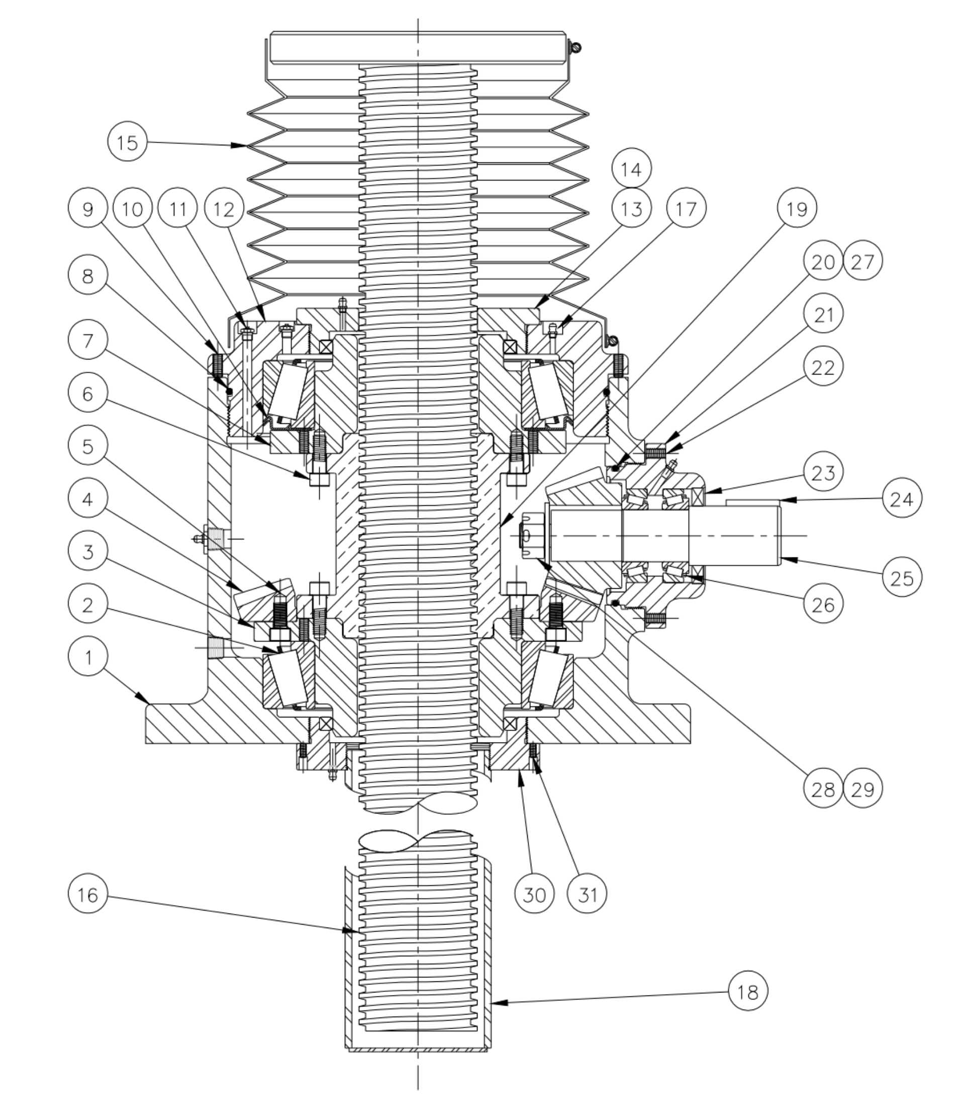
6. Bevel ball actuators are not self-locking. They will lower under load. A brake motor or other external locking system is required.
7. Bevel ball actuators are furnished with one input shaft in position #2. Jacks may be ordered with up to three input shafts located at any combination of positions # 1, 2, or 3.
8. Translating bevel ball actuators are designed for grease lubrication. The upper bearing is grease lubricated through a fitting on top of the actuator. Light oil must be applied directly to the lifting screw.
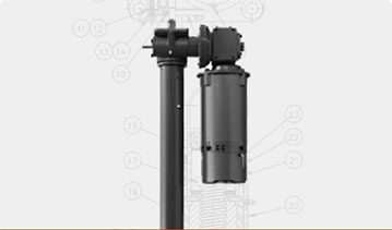
9. Typically actuators are mounted upright with the base plate parallel to the horizon.
Product Media