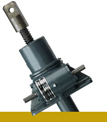
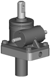
5 Ton High Lead Ball Screw Jacks
HWB65, HWB125, HWB245
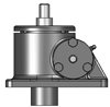
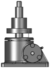
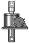
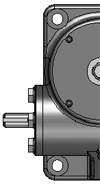
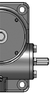
Joyce 5-ton ball screw worm gear jacks lift and precisely position loads. Upright or inverted, these jacks operate at full capacity in tension or in compression and are available in Translating and KFTN designs. High lead HWB65, HWB125, and HWB245 jacks are highly efficient and require a brake or other external locking device to hold position.
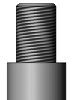
- 1 1/2” diameter ball screw
- High lead, 1”
- Available in a variety of gear set ratios
2D/3D Models
Product Media
Available Models
- Ductile iron housing
- Steel protection tube
- Ball screw, alloy steel
- Input shaft (worm), 4140 CDS
Sample Part Number:
Click on the part number to reveal additional informaton about jack designs and shaft codes.
Model Number
| 1-Ton Standard | 2-Ton Standard | 2-Ton Reverse Base Standard | 5-Ton Standard | 10-Ton Standard | 10-Ton Heavy Duty | 20-Ton Standard | 30-Ton Standard | 50-Ton Standard |
|---|---|---|---|---|---|---|---|---|
| WBL51 WBL201 |
WB62 WB122 WB242 |
RWB62 RWB122 RWB242 |
WB65 WB125 WB245 |
WBL810 WBL2410 |
WB810 WB2410 |
WB820 WB2420 |
WB1130 WB3230 |
WB1150 WB3250 |
| 1-Ton Heavy Duty | 2-Ton High Lead | 2-Ton Reverse Base High Lead | 5-Ton High Lead | 10-Ton Standard High Lead | 10-Ton Heavy Duty High Lead | 50-Ton Reverse Base | ||
| WB51 WB201 |
HWB62 HWB122 HWB242 |
RHWB62 RHWB122 RHWB242 |
HWB65 HWB125 HWB245 |
HWBL810 HWBL2410 |
HWB810 HWB2410 |
RWB1150 RWB3250 |
Important Note: *Not self-locking, may lower under load. Brake motors or external locking systems are required.
H: indicates High lead (2-ton, 5-ton and 10-ton only).
R: Reverse Base Jack (2-ton and 50-ton only).
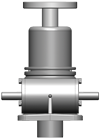
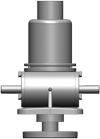
Jack Configuration
 |
 |
|
U=Upright |
I=Inverted |
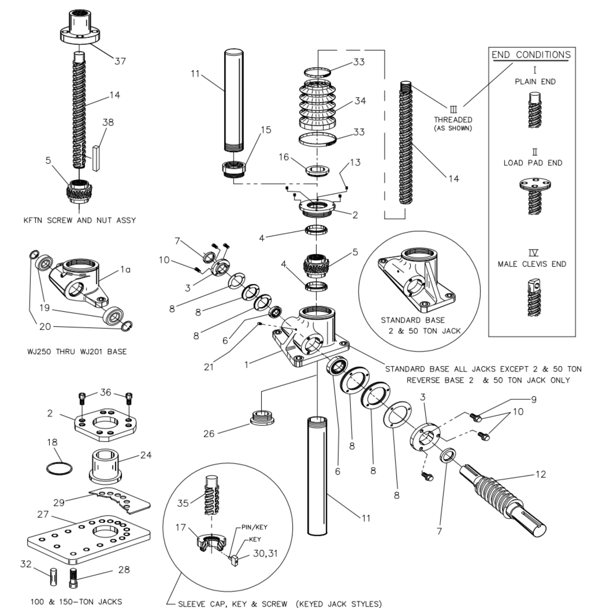
End Conditions
 |
 |
 |
 |
|
1=T1 |
2=T2 |
3=T3 |
4=T4 |
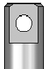
Jack Designs
 |
 |
 |
 |
|
|
S=Translating |
K=Keyed for Non Rotation** |
N=Traveling Nut |
D=Double Clevis |
R=KFTN Trunnion* |
*Standard trunnion mounts available on 2-ton through 20-ton jacks.
**Keyed for non-rotation is not a standard option. Contact Joyce/Dayton with your requirements.
Ball Screw Jack Rise
Rise is travel expressed in inches and not the actual screw length.
Left Side Shaft Code |
Right Side Shaft Code |
|
XXXX=Remove |
XXXX=Remove |
Optional Shaft Codes
Screw Stops and Boots
Screw stops are optional on ball screw jacks. When specified, the closed height of the jack and/or the protection tube length may be increased. When boots are added to ball screw jacks, the closed height of the jack may be increased.
Geared Potentiometers
POTA=0-10V (IP65)
POTB=4-20MA (IP65)
POTC=0-10V w/2 switches*
POTD=4-20MA w/2 switches*
*Optional IP65 rating available
Encoders and Electronic Limit Switches
ENCX=Encoder
ELS2=2 Position Electronic Switch
ELS4=4 Position Electronic Switch
ELS6=6 Position Electronic Switch
Motor for Systems and Direct Drive
- All standard motors are 3-phase, 208-230/460 VAC or 230/460 VAC. Other motor options are available. Specify the appropriate motor size from the chart on the right.
- Refer to the "Additional Options" chart on the preceding page as needed.
- Brake motors (M2) are recommended for jacks that are not self-locking, and jacks with double lead screws.
- If the motor frequency will be varied to provide a "soft" start an inverter duty motor may be required.
Motors
| Size | Code |
|---|---|
| 1/4 HP | K |
| 1/3 HP | A |
| 1/2 HP | B |
| 3/4 HP | C |
| 1 HP | D |
| 1-1/2 HP | E |
| 2 HP | F |
| 3 HP | L |
| 5 HP | G |
| 7-1/2 HP | H |
| 10 HP | I |
| 15 HP | J |
Motor Mounts
Ordering Example:
MMA A (Motor code from chart above)
MMA=56C
MMB=140TC
MMC=180TC
MMD=210TC
Standard motor adapters are aluminum
Mechanical Limit Switches
Ordering Example:
LA (Models) 1(Number of DPDT Switches) 3(Available Positions)
| Model | Code | Available Positions | |||||||||
|---|---|---|---|---|---|---|---|---|---|---|---|
| LS7-402 | LI |
Number of DPDT Switches NOTE: Will always be 0 for LS7 models |
1 | 2* | 3 | 4 | 5 | 6* | 7 | 8 | |
| LS8-402 | LA | Left Side Shaft Options |  |
 |
 |
 |
 |
 |
 |
 |
|
| LS8-504 | LB | ||||||||||
| LS9-502 | LC | ||||||||||
| LS9-503 | LD | Right Side Shaft Options |  |
 |
 |
 |
 |
 |
 |
 |
|
| LS9-504 | LE | ||||||||||
| LS9-505 | LF | ||||||||||
| LS9-506 | LG |
These positions are not standard. Contact Joyce/Dayton with your requirements. |
|||||||||
| LS9-507 | LH | ||||||||||
Additional Options
- X=Standard Jack, no additional options
- S=Additional Specification Required (comment as necessary)
Anti-Backlash
- A=Split Nut
- A90=A90 Design
- A95=A95 Design
Protective Boots
- B=Protective Boot
- D=Dual Protective Boot
Finishes
- F1=Do Not Paint
- F2=Epoxy Paint
- F3=Outdoor Paint Process
Motor Options
- M1=Less Motor
- M2=Brake Motor
- M3=Single Phase Motor (120VAC)
- M4=50Hz Motor
Grease/Seals
- H1=High Temperature Operation
- H2=Food Grade
Screw Stops
- ST0=Extending
- ST1=Retracting
- ST2=Both
- Specify as many options as needed
| Model | Capacity | Screw Diameter (inches) | Thread Pitch/Lead | Worm Gear Ratio | Worm Shaft Turns for 1" Travel | Tare Torque (Inches Lbs.) | Starting Torque (Inches Lbs.) | Operating Torque (Inches Lbs.) | Efficiency Rating % Approx | Screw Torque (Inches Lbs.) | Worm Holding (Inch Lbs.) | Ball Nut Life at Rated Load (Inch Screw Travel x 1000) | Basic Jack Weight (Lbs.) | Jack Weight per Inch Travel(Lbs.) |
|---|---|---|---|---|---|---|---|---|---|---|---|---|---|---|
| HWB65 | 5 ton | 1 1/2 | 1.0 | 6:1 | 6 | 10 | .065W* | .052W* @ 300 RPM |
51.1 | .177W* | .033W* | 512 | 42 | 0.7 |
| HWB125 | 5 ton | 1 1/2 | 1.0 | 12:1 | 12 | 10 | .041W* | .029W* @ 300 RPM |
45.7 | .177W* | .020W* | 512 | 42 | 0.7 |
| HWB245 | 5 ton | 1 1/2 | 1.0 | 24:1 | 24 | 10 | .029W* | .018W* @ 300 RPM |
37.2 | .177W* | .014W* | 512 | 42 | 0.7 |
Important Note: Ball Screw Jacks are not self-locking. Brake motors or external locking systems are required.
(R): Reverse Base Jack.
*W: Load in pounds.
Tare Torque: Initial torque to overcome seal and normal assembly drag. (This value must be added to starting torque or operating torque values.)
Starting Torque: Torque value required to start moving a given load (dissipates to operating torque values once the load begins moving).
Operating Torque: Torque required to continuously raise a given load at the input RPM listed. NOTE: If your actual input RPM is 20% higher or lower than the listed RPM, please refer to our JAX program to determine actual torque values at your RPM.
Screw Torque: Torque required to resist screw rotation (Translating Design Jacks) and traveling nut rotation (Keyed for Traveling Nut Design Jacks).
Worm Holding Torque: Torque required to prevent input shaft (worm) from backdriving.
Lead: The distance traveled axially in one rotation of the lifting screw.
Pitch: The distance from a point on a screw thread to a corresponding point on the next thread, measured axially.